The Arduino MKR NB 1500 is another modified device of the Arduino MKR family which offers network connectivity. This board provides narrowband communication for IoT-related devices.
Arduino MKR NB 1500 has become an integral part in the development of many automation and embedded projects. This board is an open-source platform which means we can modify the hardware and software of the board according to our requirements. This modification can be done using Arduino Integrated Development Environment or Arduino IDE. C and C++ are the programming languages which are used in programming the Arduino IDE.
In the Arduino MKR NB 1500, we can also interface a micro-sim with the board, however, the micro-sim is not provided with the board so we have to purchase it separately.
The Arduino MKR NB 1500 has coverage of most of the regions of Asia, Europe, South America, and North America.
The Arduino MKR NB 1500 is easy to access from wherever we want as it is compatible with the Arduino IoT cloud and all these features of the Arduino MKR NB 1500 make it a great choice for inventors and electrical enthusiasts.
In this article, we will be going through the features, specifications, and pin description of the Arduino MKR NB 1500, so let’s get started.
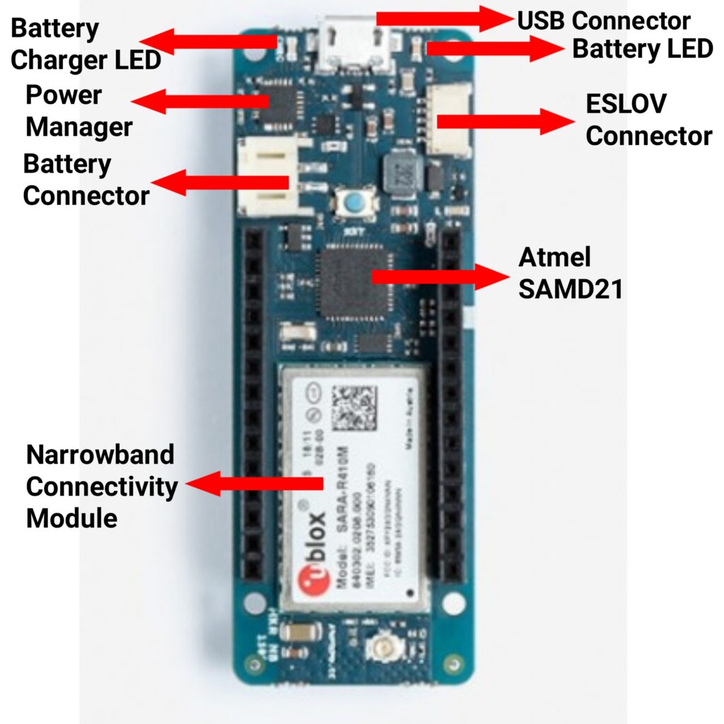
Board Layout OF Arduino MKR NB 1500
Microprocessor
Arduino MKR NB 1500 is a microcontroller board which operates on Arm Cortex – M0 32-bit SAMD21 processor. The Arm Cortex – M0 32-bit SAMD21 is a low-power but powerful processor.
Cryptochip
The Arduino MKR NB 1500 has a Crypto Chip which is ATECC508A. The ATECC508A is the first crypto chip which has an integrated ECDH or Elliptic Curve Diffie–Hellman key agreement.
It is used for the encryption and decryption of digital signals which are sent during the transmission. It is also used to encrypt and decrypt the IoT nodes which are used in building a sensor network for agricultural projects and other applications.
The ATECC508A can protect the storage of up to 16 keys, Data, or Certificates.
Narrowband Connectivity Module
The Arduino MKR NB 1500 contains a narrowband connectivity module which is uBlox SARA-R410M-02B. It is a low-power chipset which is available on the board. The uBlox SARA-R410M-02B can connect to the bands of the IoT LTE cellular range like LTE-M, NB-IoT, and EGPRS networks. With the help of this module, it is possible to send and receive messages.
USB Connector
The Arduino MKR NB 1500 consists of a Micro USB port for supplying operating voltage to the board.
Clock Speed
The Clock frequency of the Arduino MKR NB 1500 processor is 48 MHz while the clock frequency of the Real Time Clock or RTC is 32.768 kHz.
Memory
In Arduino MKR NB 1500 the microprocessor has a total of 256 KB of Flash memory and 32KB SRAM.
Battery Charger LED
There is a battery charger LED available on the Arduino MKR NB 1500 board which turns on when there is an input voltage supply to the board.
Specification of Arduino MKR NB 1500
The specifications of Arduino MKR NB 1500 are as follows:-
| Name | Arduino MKR NB 1500 |
|---|---|
| SKU | ABX00019 |
| Compatibility | MKR |
| Microcontroller | SAMD21 Cortex-M0+ 32 bit low power ARM MCU |
| USB connector | Micro USB (USB-B) |
| Built-in LED Pin | 6 |
| Digital I/O Pins | 8 |
| Analog Input Pins | 7 (ADC 8/10/12 bit) |
| External interrupts | 10 (0, 1, 4, 5, 6, 7, 8 ,9, A1, A2) |
| NB-IoT / LTE-M | u-blox SARA-R410M-02B |
| SIM Card | MicroSIM (not included with the board) |
| Working region | Multi region |
| Carrier frequency | LTE bands 1, 2, 3, 4, 5, 8, 12, 13, 18, 19, 20, 25, 26, 28 |
| Data Rate (LTE M1 Half-Duplex) | UL 375 kbps / DL 300 kbps |
| Data Rate (LTE NB1 Full-Duplex) | UL 62.5 kbps / DL 27.2 kbps |
| Secure element | ATECC508A |
| UART | Available |
| I2C | Available |
| SPI | Available |
| I/O Voltage | 3.3V |
| Input Voltage (nominal) | 5-7V |
| DC Current per I/O pin | 7 mA |
| Supported battery | Li-Po Single Cell, 3.7V, 1500mAh minimum |
| Battery connector | JST PH |
| Power Consumption (LTE M1) | min 100 mA / max 190 mA |
| Power Consumption (LTE NB1) | min 60 mA / max 140 mA |
| Processor | 48 MHz |
| RTC | 32.768 kHz |
| Memory of processor | 256KB Flash, 32KB S RAM |
| Weight | 32 g |
| Width | 25 mm |
| Length | 67.6 mm |
Pins Description OF Arduino MKR NB 1500
Power Pins
- Vin
This pin is used for supplying an input voltage of 5 volts. The input voltage is a direct current supply voltage. The input voltage is used to regulate the integrated circuits which are used in the connections. When this pin is in use the USB pin is disconnected. Vin is also known as the primary voltage source on the Arduino MKR
NB 1500 board.

| S.NO | Pin Number | Type | Pin Name |
| 1 | VIN | Power | Supply voltage |
- 5v pin
The 5v pin is used as the output for external components. The output is 5v. This pin is used only when the board is powered by USB or the power source of the 5v pin is a USB connector.

| S.NO | Pin Number | Type | Pin Name |
| 2 | +5V | Output or Input | +5V (Input from External Power Supply |
- 3V3 Pin
The 3V3 pin is used as an output pin. This pin generates an output voltage of 3.3 volts.

| S.NO | Pin Number | Type | Pin Name |
| 3 | 3V3 | Output | +3.3V Output |
- Reset Pin
The RESET pin is used to reset the board. For resetting the board we have to pull down this pin to LOW.

| S.NO | Pin Number | Type | Pin Name |
| 4 | RESET | Input | Reset ( Active Low) |
- GND pin
This pin is used as the ground pin of the board.

| S.NO | Pin Number | Type | Pin Name |
| 5 | GND | Power | Supply Ground |
Digital Pins
- Digital I/O Pins
There are a total of 22 digital input/output pins available on the Arduino MKR NB 1500. The digital pins are used as an input or output according to the requirement. The digital pins are only able to read two values which are:-
- High
- Low
However, we can use 1 for the high state and 0 for the low state. When these pins receive 0V they are in a LOW state and when they receive 5V they are in a HIGH state.
The digital pins on the Arduino MKR NB 1500 are from D0 to D21

| S.NO | Pin Number | Type | Pin Name |
| 1 | D0 | I/O | Digital I/O Pin |
| 2 | D1 | I/O | Digital I/O Pin |
| 3 | D2 | I/O | Digital I/O Pin |
| 4 | D3 | I/O | Digital I/O Pin |
| 5 | D4 | I/O | Digital I/O Pin |
| 6 | D5 | I/O | Digital I/O Pin |
| 7 | D6 | I/O | Digital I/O Pin |
| 8 | D7 | I/O | Digital I/O Pin |
| 9 | D8 | I/O | Digital I/O Pin |
| 10 | D9 | I/O | Digital I/O Pin |
| 11 | D10 | I/O | Digital I/O Pin |
| 12 | D11 | I/O | Digital I/O Pin |
| 13 | D12 | I/O | Digital I/O Pin |
| 14 | D13 | I/O | Digital I/O Pin |
| 15 | D14 | I/O | Digital I/O Pin |
| 16 | D15 | I/O | Digital I/O Pin |
| 17 | D16 | I/O | Digital I/O Pin |
| 18 | D17 | I/O | Digital I/O Pin |
| 19 | D18 | I/O | Digital I/O Pin |
| 20 | D19 | I/O | Digital I/O Pin |
| 21 | D20 | I/O | Digital I/O Pin |
| 22 | D21 | I/O | Digital I/O Pin |
Analog Pins
There are a total of 7 analog pins available on the Arduino MKR NB 1500 board. Analog Input Pins are used to take the signal from analog sensors and then convert it into a digital value. These pins can receive any value, unlike digital pins. It can receive value not only in the high or low states but in other forms also. The analog pins of the board are from Pin A0 to Pin A06.
The Analog pins of the Arduino MKR NB 1500 Board are as follows:-

| S.NO | Pin Number | Type | Pin Name |
| 1 | A0 | Input | Analog Input Channel 0 |
| 2 | A1 | Input | Analog Input Channel 1 |
| 3 | A2 | Input | Analog Input Channel 2 |
| 4 | A3 | Input | Analog Input Channel 3 |
| 5 | A4 | Input | Analog Input Channel 4 |
| 6 | A5 | Input | Analog Input Channel 5 |
| 7 | A6 | Input | Analog Input Channel 6 |
PWM Pins
There are 13 pins also known as Pulse Width Modulation pins. The work of these PWM pins is to convert the digital inputs to analog output. These pins provide 8-bit PWM output with the analogWrite () function. The PWM pins of the Arduino MKR NB 1500 board are 0,1,2,3,4,5,6,7,8,10,12, A3, and A4.

| S.NO | Pin Number | Type | Pin Name |
| 1 | D0/PWM | I/O | Digital I/O Pin Pulse Width Modulation Pin |
| 2 | D1/PWM | I/O | Digital I/O Pin Pulse Width Modulation Pin |
| 3 | D2/PWM | I/O | Digital I/O Pin Pulse Width Modulation Pin |
| 4 | D3/PWM | I/O | Digital I/O Pin Pulse Width Modulation Pin |
| 5 | D4/PWM | I/O | Digital I/O Pin Pulse Width Modulation Pin |
| 6 | D5/PWM | I/O | Digital I/O Pin Pulse Width Modulation Pin |
| 7 | D6/PWM | I/O | Digital I/O Pin Pulse Width Modulation Pin |
| 8 | D7/PWM | I/O | Digital I/O Pin Pulse Width Modulation Pin |
| 9 | D8/PWM | I/O | Digital I/O Pin Pulse Width Modulation Pin |
| 10 | D10/PWM | I/O | Digital I/O Pin Pulse Width Modulation Pin |
| 11 | D12/PWM | I/O | Digital I/O Pin Pulse Width Modulation Pin |
| 12 | A3/PWM | Input | Analog Input Channel 3 Pulse Width Modulation Pin |
| 13 | A4/PWM | Input | Analog Input Channel 4 Pulse Width Modulation Pin |
Communication Pins of Arduino MKR NB 1500
- SPI Pins
The Arduino MKR NB 1500 board supports the “Serial-Peripheral Communication Protocol” or SPI. The SPI protocol is used to develop communication between the controller device and its peripheral devices. Three pins are needed for SPI communication protocol which are:-
- MISO – It stands for Master Input/Slave Output. This data line sends data to the master device.
- MOSI – It stands for Master Output/Slave Input. This data line is used for sending data to slaves/peripheral devices.
- SCK – This pin is used to synchronize the data transfer between the master and slave device.
SPI pins on the board are D08 which is used as the MOSI pin, D09 which is used as the SCK pin, and D10 which is used as the MISO pin.
The Pins MISO, and MOSI are also known as CIPO and COPI which stand for “Controller In Peripheral Out” and “Controller Out Peripheral In” respectively.

| S.NO | Pin Number | Type | Pin Name |
| 1 | D08/MOSI | I/O | Master Out Slave In |
| 2 | D09/SCK | Output | Clock From Master To Slave |
| 3 | D10/MISO | I/O | Master In Slave Out |
- I2C Pins
The Arduino MKR NB 1500 board contains the I2C communication protocol. It stands for “Inter-Integrated Circuit.” It is a two-wire serial communication protocol. It uses two pins for communication purposes. One of them is used to send data while the other pin is used to receive data.
The two pins of the I2C protocol are “Serial Clock Pin(SCL)” and “Serial Data Pin(SDA)”.
- SCL – It is defined as the line or pin which transfers the clock data. SCL pin is used to synchronize the shift of data in between two devices. This signal is generated by the master device.
It is a clock line.
- SDA – It is defined as the line or pin which is used by slave devices to send and receive data. It is a data line.
I2C pins on the board are D11 which is SDA and D12 which is SCL.

| S.NO | Pin Number | Type | Pin Name |
| 1 | D11/SDA | I/O | Digital I/O Pin Serial Data Pin |
| 2 | D12/SCL | I/O | Digital I/O Pin Serial Clock Pin |
- UART Pin
The Arduino MKR NB 1500 consists of a universal asynchronous receiver-transmitter communication protocol which is used for serial communication of data. It needs two pins for communication purposes which are Rx and TX.
- Rx – This pin is used to transmit the serial data.
- TX – This pin is used to receive the serial data.
UART pins on the board are D13 which acts as RX pin and D14 which act as TX pin.

| S.NO | Pin Number | Type | Pin Name |
| 1 | D13/RX | I/O | Digital I/O Pin Serial RX Pin |
| 2 | D14/TX | I/O | Digital I/O Pin Serial TX Pin |
AREF
The AREF pin is used to provide the external reference voltage to the analog pins for the analog-to-digital conversion process.

| S.NO | Pin Number | Type | Pin Name |
| 1 | AREF | Input | ADC reference |
LED BUILT-IN
This LED blinks whenever the board is powered up or power is supplied to the board.