The Serial Peripheral Interface SPI protocol is a Serial data protocol. It is a synchronous serial protocol that is used by microcontrollers for communicating with other peripheral devices at very high speeds over short distances.
Serial Peripheral Interface or SPI operates at full duplex which allows devices to send and receive data simultaneously. As compared to I2C or UART communication protocols
The SPI Protocol is the fastest of all of them because it provides high data transmission rates of 8 Mb and more. The reason behind the fast transmission rates is its simple protocol. The Data or clock lines are shared between all of the connected devices and each device will require a unique address wire.
Serial Peripheral Protocol is used where the speed of transmission is important. It is used in SD cards, display modules, and in instruments where information updates and changes quickly for example – thermometers, etc.
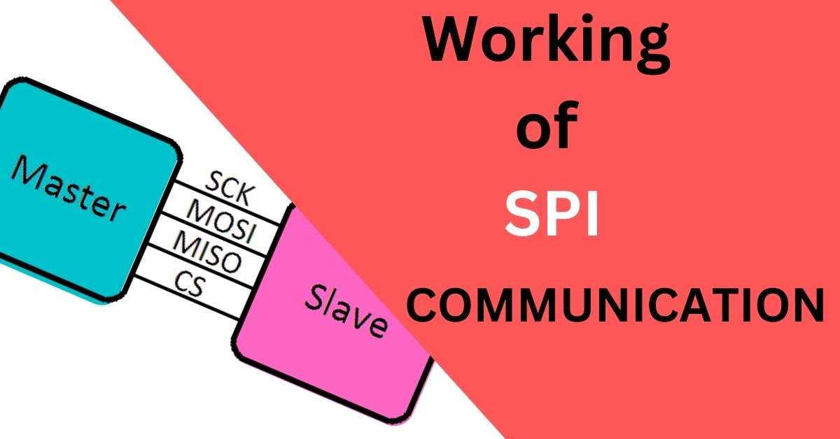
The SPI uses master and slave architecture in which one master device controls another slave device. However, it can only be used with a single master device with a maximum number of four slaves.
The SPI Protocol has 4 lines which are:-
MISO
MISO stands for “Master In Slave Out”. In this, the slave pin is used for sending the data to the master.
MOSI
MOSI stands for “Master Out Slave In”. In this, the master pin is used for sending the data.
SS
SS stands for ‘Slave Select”. It is the Slave Select line, which is used by the master. It acts as the enable line when the SS line = Low. The device interfaces with the master if the Slave Select line = High.
SCK
SCK stands for “Serial Clock”. These are the clock pulses, which are used to synchronize the transmission of data.
In master mode, it works as the output clock while In slave mode, it works as the input of the clock generator. The data generated by the master is synchronized by the SCK.
Chip Select pin (CS)
It is allocated to each device that the Controller will use to enable and disable specific devices and avoid false transmissions due to line noise.
Since SPI Protocol uses four pins for communication hence it is sometimes called the Four Wire Interface.
Working of Serial Peripheral Interface Communication SPI Protocol:-
The Clock:-
The clock signal is used to synchronize the output of data bits coming from the master device. One bit of incoming data is transferred in each clock cycle so that the speed of the data transfer is determined by the frequency of the clock signal.
The SPI protocol is always initiated by the master device since the master is responsible for configuring and generating the clock signal.
Any communication protocol which uses clock signals is considered synchronous. The SPI protocol is one of them. The process of modification of clock pulses can be carried out by using the properties of clock polarity and clock phase.
These two properties are responsible for when the bits are output and when they are sampled. The clock polarity can be determined by the master device to allow for bits to be the output and sampled on either the rising edge or falling edge of the clock cycle while the clock phase can be set for output and sampling to occur on either the rising edge or falling edge of the clock cycle.
The clock phase determines the clock transition i.e. rising (LOW to HIGH) or falling (HIGH to LOW), at which the data is transmitted while the clock polarity determines the state of the clock. When CPOL is LOW, the clock generated by the Master i.e. SCK is LOW when it is in an idle state and becomes HIGH during the active state and when CPOL is HIGH, SCK becomes HIGH for the idle state and LOW for the active state.
Slave Select:-
The selection of slave devices is Carried out by the master device. The master device will choose the slave device with which it wants to communicate by setting the Chip Select or Slave Select line to a low voltage level.
The chip select or slave select line will remain at a high voltage level in an idle or non-transmitting state.
Multiple Slaves:-
SPI Protocol can operate in multi-slave environments too. In this system, multiple slaves are controlled by a single master. The connection of a multi-slave system depends upon the number of slaves selected or chip select pins available on the master device.

- If there is only one CS/SS pin present on the master device then multiple slaves can be wired to the master by daisy-chaining(Priority establishing method, the device with the highest priority is placed in the first position, followed by lower-priority devices up to the device with the lowest priority, which will be placed at last position in the chain).
- If there are multiple CC/SS pins present then multiple slave devices can be connected in parallel connection.
MOSI And MISO:-
Once the connection of the master and slave device is completed we will start the communication. The master device sends the data to the slave device using MOSI( Master Out Slave In ) pin. The data sent by the master device to the slave device is usually sent with the most significant bit first.
The slave device can also send data to the master device using MISO( Master In Slave Out ) pin. The data sent by the slave device to the master device is sent with the least significant bit first.
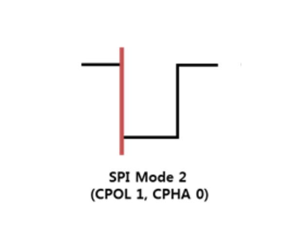
Modes OF Operations Of SPI:-
The modes of operation of SPI are determined by the Clock Polarity(CPOL) and Clock Phase(CPHA).
There are in total of 4 modes of operations of SPI which are:-
- Mode 0
- Mode 1
- Mode 3
- Mode 4
Mode 0 –
Mode 0 occurs when the Clock Polarity is LOW and the Clock Phase is 0 (i,e. CPOL = 0 and CPHA = 0). During this mode, the data transmission occurs during the rising edge of the clock.

Mode 1 –
Mode 1 occurs when the Clock Polarity is LOW and the Clock Phase is 1 (i,e. CPOL = 0 and CPHA = 1). During This mode, data transmission occurs during the falling edge of the clock.

Mode 2 –
Mode 2 occurs when the Clock Polarity is HIGH and the Clock Phase is 0 (i,e. CPOL = 1 and CPHA = 0). During this mode, the data transmission occurs during the falling edge of the clock.
Mode 3 –
Mode 3 occurs when the Clock Polarity is High and the Clock Phase is 1 (i,e. CPOL = 1 and CPHA = 1). During this mode, the data transmission takes place during the rising edge of the clock.

Applications Of SPI Protocol:-
- It can be used in memory i,e. SD Card, MMC, EEPROM, and Flash.
- It can be used in sensors, ie. Pressure and Temperature.
- It can be used in control devices i,e. ADC, DAC, digital POTS, and Audio Codec.
- It can be used in Camera Lens Mount
- In Touchscreens
- In LCD, Video game controllers, etc.
Practical Use Of SPI Communication Protocol:-
In this practical explanation of the SPI protocol, we will design an MCP4131 digital potentiometer using the SPI protocol and Arduino Uno.
What is MP4131 Digital Potentiometer:-
The MCP4131 is a resistor network with a potentiometer pinout.

The SPI Protocol pins are as follows:-
- MISO = Serial Data Input (SDI) at pin 3 (combined with MOSI)
- MOSI = Serial Data Output (SDO) at pin 3 (combined with MISO)
- SCLK = Serial Clock (SCK) at pin 2
circuit Diagram:-

Program For Digital Potentiometer:-
#include <SPI.h>

void setup() {
  pinMode(10, OUTPUT); // set the SS pin as an output
  SPI.begin();         // initialize the SPI library
  Serial.begin(9600);
}
void loop() {

  digitalWrite(10, LOW);            // set the SS pin to LOW

  for(byte wiper_value = 0; wiper_value <= 128; wiper_value++) {

    SPI.transfer(0x00);             // send a write command to the MCP4131 to write at registry address 0x00
    SPI.transfer(wiper_value);      // send a new wiper value

    Serial.println(analogRead(A0)); // read the value from analog pin A0 and send it to serial
    delay(1000);
  }

  digitalWrite(10, HIGH);           // set the SS pin HIGH
}
Code explanation
#include <SPI.h>
It is the required SPI library that we need for this project. With the help of the “#include” command we import the library.
SPI.Begin()
With the help of this function, we will initialize the SPI bus. The SPI.Begin() sets the MOSI, MISO, and SS/CS pin modes to OUTPUT and sets the MOSI and SCLK to LOW, and sets the SS/CS pin to HIGH.
digital.write(10, Low);
Before sending the data to a slave device we have to keep in mind that we must pull the master device’s CS/SS line to low.
SPI.Transfer()
This function is used to send the commands to MCP4131. This function also returns the data received from MCP4131. The value parameter is the amount of data that we want to send over the SPI.
Serial.println(analogRead(A0))
To visualize or display the output resistance of MCP4131 we need to read the voltage at pin AO which is an analog pin of an Arduino and then print it to the serial monitor.
digitalWrite(10, HIGH);
For telling the MCP4131 that we are done communicating with it we use the digitalWrite(10, HIGH) function. We put this function at the end of the loop() section.
Advantages of SPI:-
- SPI is very simple to implement and the hardware requirements are not that complex.
- No start and stop bits are there, so the data can be streamed continuously without any interruption.
- Supports full–duplex communication at all times.
- Almost two times more data transfer rate than I2C.
- There is no need for a unique address of the slave in this protocol.
- Signals are unidirectional.
- Separate MISO and MOSI lines, so data can be sent and received at the same time.
Disadvantages Of SPI protocoal:-
- Each additional slave requires an additional dedicated pin on the master for CS or SS.
- No acknowledgment that the data has been successfully received.
- Usually, it supports only one master.
- The slowest device determines the speed of transfer.
- No form of error checking like the parity bit in UART.
- It can be used only from a short distance.
Frequently Asked Questions:-
- Who invented or developed SPI?
SPI was developed by Motorola in 1980.
- What is the speed of SPI?
The speed of SPI is up to 60 Mbps.F
- Which one has higher throughput SPI or I2C?
SPI is faster than I2C because the bit rate of I2C is 100 kbps and for SPI it is 1 Mbps.
- Is bus arbitration supported in SPI?
No, bus arbitration is not supported by SPI.
8 thoughts on “How (Serial Peripheral Interface) SPI Protocol works”