
The ESP32 is a powerful Camera Module. Under this column, we’ll deeply discuss the ESP32 cam module, set up a video streaming server, and use it as a Home Security Camera. We already know how to program ESP8266 nodemcu.
Introduction to ESP32 Camera
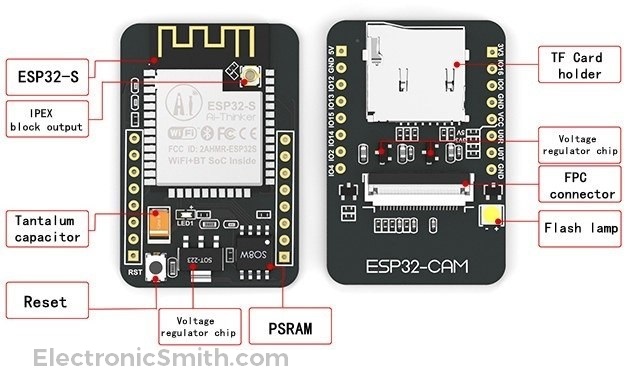
The camera breakout board is based on ESP32-S WI-Fi enabled microcontroller. It has a TF card holder where you can attach a memory card to take photos and recording the videos.
Specification
- The smallest 802.11b/g/n Wi-Fi BT SoC module.
- Low power 32-bit CPU, can also serve as the application processor.
- Up to 160MHz clock speed, summary computing power up to 600 DMIPS.
- Built-in 520 KB SRAM, external 4MP SRAM.
- Supports UART/SPI/I2C/PWM/ADC/DAC.
- Support OV2640 and OV7670 cameras, built-in flash lamp.
- Image Wi-FI upload.
- TF card.
- Supports multiple sleep modes.
- Embedded Lwip and free RTOS.
- Supports STA/AP/STA+AP operation mode.
- Support Smart Config/AirKiss technology.
- Support for serial port local and remote firmware upgrades (FOTA).
Pinout
The ESP32 camera has a total of 10 GPIO that works with 3.3v and 5v both. I recommend 5V for operations of this project.

Material Required
| Hardware | Quantity |
| ESP32-Cam Module | 1 |
| FTDI Programmer | 1 |
| Jumper Wires | APR |
| Software | Link |
| Arduino IDE | Click Here! |
Hardware Setup and Connection of ESP32 Camera
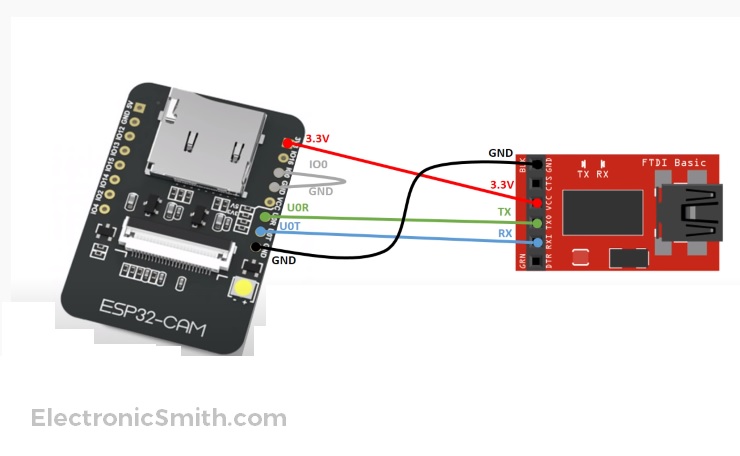
ESP32 doesn’t have an onboard FTDI programmer and we required an FTDI programmer to program the board.
| FTDI | ESP32-CAM |
| TX | UDR |
| RX | UDT |
| IO0 | GND |
| 3.3V | 3.3V |
| GND | GND |
Software Setup
We already know how to install the Arduino IDE and its setup. Here, we will only focus to add ESP32 board in IDE and program it.
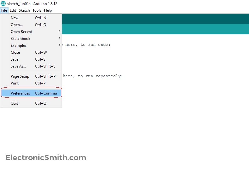
- Go to the file option and click on Preferences.
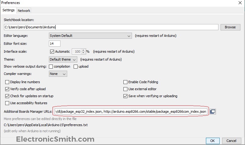
- Copy the below-mentioned link and paste it in the additional board manager’s URL. This link contains ESP32 and ESP8266 board links. If you have any other board URL, keep a comma(,) in between, and then paste the link.
https://dl.espressif.com/dl/package_esp32_index.json, http://arduino.esp8266.com/stable/package_esp8266com_index.json
- Then, go to Tools Board and open Board Manager. Open it to download the board and install it.
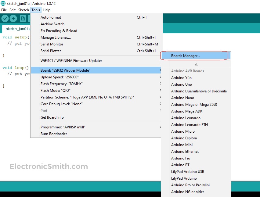
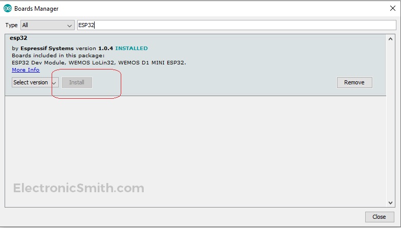
- Type in Search bar ESP32 and install the first option ESP32 by Espressif Systems. I had it already installed in my system.
- Let’s open a example code to test if everything is okay. Go to file option examples, ESP32, Camera, and CameraWebServer.

- The Camera webserver example will open now. Here, we need to modify a few things. Commend the #define CAMERA_MODEL_WROVER_KIT and uncomment the #define CAMERA_MODEL_AI_THINKER. Also, change the SSID and password of your Wi-Fi network. Connect the FTDI with computer and press reset to enable the flash mode.

- Then, again go to the Tools board and search for ESP32 Wrover Module. Be careful and choose the correct board and upload the code. In case you get any errors, change upload speed to “256000“, Flash Frequency to “80Mhz“, Flash Mode “QIO“, and Partition Scheme “Huge APP(3MB No OTA/1MB SPIFFS)) “.

- After uploading, remove the jumper wire between GND and IO0 open serial monitor and press the reset button. It will disable the flash mode and connect to your Wi-Fi and prints the connected IP Address.

Browser Setup for ESP32 Camera
Copy the HTTP link and paste it to your browser. If you get this page, your ESP cam setup is done. Insert the SD card, start recording and your wireless security cameras are ready to use. Install them on your door and CCTV security cameras are all set to perform You can open this page on a mobile phone and simply copy the same URL and paste in a mobile browser. Now you can access your wireless security cameras using mobile phones.

Error and Corrections
E][camera.c:1049] camera_probe(): Detected camera not supported.
[E][camera.c:1249] esp_camera_init(): Camera probe failed with error 0x20004
If you get the above error use a separate 5V power supply and make sure to change the board to #define CAMERA_MODEL_AI_THINKER and do the exact settings as I did in the screenshot attached above.