The Arduino Uno R3 is a great starting point for your projects. It is the most popular board in the Arduino family. It has two variants one consists of a 28-pin DIP Microcontroller while the other consists of 32 lead Quad Flat Package Microcontroller. The microcontroller on the Arduino Uno R3 is the Atmega328P, which contains everything needed to support the microcontroller.
Arduino Uno R3 Board Layout
It has a Type-B USB connector on the left side of the board. It is used for powering the board as well as programming the Microcontroller. Arduino Uno is similar to Arduino Nano but extended version.

DC jack-It consists of a 2.1 mm DC jack which is used to provide an external power supply.
Memory-It consists of 32 KB ISP flash memory with read-while-write capabilities, 2 KB SRAM(Static RAM), 1 KB of EEPROM, and 23 general-purpose I/O pins.
Voltage Regulator-The voltage regulator is used to convert any input voltage to 5V. The primary work of a voltage regulator is to control the voltage level in the Arduino Board.
Crystal Oscillator– The Crystal oscillator has a frequency of 16MHz. It is used to provide the clock signal to the microcontroller. It provides the basic timing and control to the board.
RESET Button–The Reset button is used to reset the board.
ICSP header– ICSP stands for “In-Circuit Serial Programming.”
These pins are used to program the Arduino board’s firmware.
Arduino uno dimensions
| Length | 68.6mm |
| width | 53.4mm |
| Weight | 25g |
| Holes | 3×3.2mm |
Specifications Of Arduino Uno R3
The specifications table of Arduino Uno R3 are as follows:-
| MISO | Master In Slave Out (Input or Output) |
| 5V | Supply |
| SCK | Clock (from Master to Slave) |
| MOSI | Master Out Slave In (Input or Output) |
| RESET | Reset (Active LOW) |
| GND | Ground |
| MCU | ATmega328P |
| Architecture | AVR |
| Operating Voltage | 5V |
| Input Voltage | 6V – 20V (limit)7V – 12V (recommended) |
| Clock Speed | 16 MHz |
| Flash Memory | 32 KB (2 KB of this used by bootloader) |
| SRAM | 2 KB |
| EEPROM | 1 KB |
| Digital IO Pins | 24 (of which 6 can produce PWM) |
| Analog Input Pins | 6 |
| Communication protocol | UART x 1, SPI x 1, I2C x 1 |
| DC Current per I/O Pin | 20 mA |
| DC Current for 3.3V Pin | 50 mA |
| ICSP Header | 2 |
| LED_BUILTIN | Pin No. 13 |
| Power Sources | Power Jack, USB port, Vin pin |
| Length | 68.6 mm |
| Width | 53.4 mm |
| Weight | 25 g |
Arduino Uno R3 Pinout Description
Now, let us assume some basic numbering the RX is Pin 1, TX is Pin 2, D2 is Pin 3, and so on.

On the other hand, NC is Pin 19, IOREF is Pin 20, etc. Overall, there are 32 pins on the Arduino UNO Board.
| Pin Number | Pin Name | Description | Alternative Functions |
| 1 | RX / D0 | Digital IO Pin 0Serial RX Pin | Generally used as RX |
| 2 | TX / D1 | Digital IO Pin 1Serial TX Pin | Generally used as TX |
| 3 | D2 | Digital IO Pin 2 | |
| 4 | D3 | Digital IO Pin 3 | Timer (OC2B) |
| 5 | D4 | Digital IO Pin 4 | Timer (T0/XCK) |
| 6 | D5 | Digital IO Pin 5 | Timer (OC0B/T1) |
| 7 | D6 | Digital IO Pin 6 | |
| 8 | D7 | Digital IO Pin 7 | |
| 9 | D8 | Digital IO Pin 8 | Timer (CLK0/ICP1) |
| 10 | D9 | Digital IO Pin 9 | Timer (OC1A) |
| 11 | D10 | Digital IO Pin 10 | Timer (OC1B) |
| 12 | D11 | Digital IO Pin 11 | SPI (MOSI) Timer (OC2A) |
| 13 | D12 | Digital IO Pin 12 | SPI (MISO) |
| 14 | D13 | Digital IO Pin 13 | SPI (SCK) |
| 15 | GND | Ground | |
| 16 | AREF | Analog Reference | |
| 17 | SDA / D18 | Digital IO Pin 18 | I2C Data Pin |
| 18 | SCL / D19 | Digital IO Pin 19 | I2C Clock Pin |
| 19 | NC | Not Connected | |
| 20 | IOREF | Voltage Reference | |
| 21 | RESET | Reset (Active LOW) | |
| 22 | 3V3 | Power | |
| 23 | 5V | +5V Output from regulator or +5V regulated Input | |
| 24 | GND | Ground | |
| 25 | GND | Ground | |
| 26 | VIN | Unregulated Supply | |
| 27 | A0 | Analog Input 0 | Digital IO Pin 14 |
| 28 | A1 | Analog Input 1 | Digital IO Pin 15 |
| 29 | A2 | Analog Input 2 | Digital IO Pin 16 |
| 30 | A3 | Analog Input 3 | Digital IO Pin 17 |
| 31 | A4 | Analog Input 4 | Digital IO Pin 18 I2C (SDA) |
| 32 | A5 | Analog Input 5 | Digital IO Pin 19 I2C (SCL) |
Table of the pins of the ICSP Connector
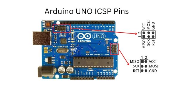
| MISO | Master In Slave Out (Input or Output) |
| 5V | Supply |
| SCK | Clock (from Master to Slave) |
| MOSI | Master Out Slave In (Input or Output) |
| RESET | Reset (Active LOW) |
| GND | Ground |
How to power up Arduino Uno R3
There are two ways to power up the Arduino UNO board
1) Using the Type-B USB Connector
2) Another way is to provide an unregulated supply in the range of 6V to 20V to the Vin pin(Pin number 26) or DC jack of the Arduino UNO.

Different Memories Of Arduino Uno
Different memories of Arduino Uno are as follows:-
- 32KB of flash memory.
- 2KB of SRAM.
- 1KB of EEPROM.
Input and Output Pins of Arduino UNO
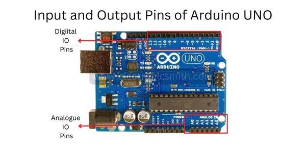
Digital Input Output Pins
From the 32 pins, 22 pins are associated with input and output. D0 – D13 are associated with I/O pins.
It can be configured as per your application by using pinMode(), digitalRead(), and digitalWrite() functions.
I/O pins are capable of sourcing or sinking 20mA of current. It also consists internal pull-up resistor.
The value of the internal pull-up resistor will be in the range of 20KΩ to 50KΩ.
Analog Input Output Pins
It also has 6 Analog Input Pins (A0 to A5).
All of these analog input pins can be read using analogRead() function.
The Digital IO pins numbered 3, 5, 6, 9, 10, and 11 are capable of producing 8-bit PWM Signals.
PWM Pins

PWM stands for “PULSE WIDTH MODULATION”. The digital pins 3,5,6,9,10, and 11 are the PWM Pins. They have an additional feature PWM that’s why it is called PWM Pins.
GND Pins
There are 5 GND pins available on the board.
Communication Interfaces Pins available on Arduino UNO

Arduino UNO supports 3 diffrent types of communication interfaces:-
- Serial
- I2C
- SPI
The digital IO pins 0 and 1 are used as Serial RX and TX pins which are used to receive and transmit data.
The pins A4 and A5 have alternative functions and they can be configured as SDA (A4) and SCL (A5) to support I2C or I2C or Two Wire Interface (TWI) communication.
The digital IO Pins 10, 11 12, and 13 can be configured as SPI pins
12 thoughts on “Pinout, Function and working of Arduino Uno R3”