Introduction
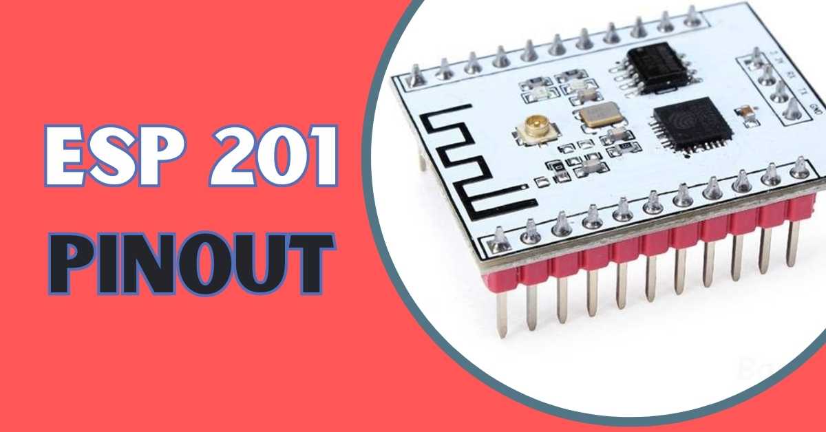
ESP 201 module is another ESP8266 board which has many similarities with the ESP-12E module. The factor which makes it different from another module is that it supports a PCB antenna as well as an external antenna using a U.FL connector.
ESP 201 has firmware by AI Thinker which is a third-party manufacturer of Espressif chips. It has an extra io port and it is a breadboard family. For this purpose, the middle pins are needed to be de-soldered and soldered to make it breadboard friendly.
This board is a powerful and programmable WiFi SoC with integrated TCP/IP protocol. With ESP 201 it is possible to host an application or access an existing application via the Internet. It comes with pre-programmed AT firmware which means you can directly connect it to Arduino to get WiFi ability.
The ESP 201 uses the ESP8266EX chip which was developed for use in mobile, wearable objects, and Internet OF Things applications for attaining maximum functions with low power consumption.
That is all in the introduction of the ESP 201 module, now let us discuss about the onboard components of the ESP 201 module.
On Board Components

- Microprocessor – As mentioned earlier the ESP 201 is based on the ESP8266 processor.
- ESP8266EX SoC – ESP8266EX SoC is a wifi chip which is available on the board and can go up to 80 – 240 MHz of frequency.
- Antenna – ESP 201 has an in-built PCB antenna which is used for connecting the board to wifi connectivity. We can also use an external antenna using the U-LP
- Memory – The ESP 201 board comes with 8 MB of embedded SPI flash memory which is needed for storing the program and firmware.
- Power LED – There is an inbuilt power led present in the ESP 201 module which is red in color and it will start blinking when the board is connected to a power supply.
- U.FL Connector – An in-built U.FL connector is present on the board which is used to connect an external antenna to the ESP 201 board.
Board Features
| Board | ESP 201 |
| Processor | ESP8266EX |
| Antenna | Inbuilt, External using U.FL Connector |
| Board Dimension | 25mm × 35mm |
| I/O Port | 17 |
| ADC | 1 |
| Application | Standalone |
| Interfaces | UART, SPI, SDIO 1.2/2.0 |
| Flash Memory | 8MB |
| PWM | 4 |
Power Consumption OF ESP 201
| Power supply | 2.2-3.6v |
| Current Consumption | 70.5mA |
| I/O voltage | 0-3.3v |
| I/O Source Current | 12mA |
| Modem sleep | 15mA |
| Light sleep | 0.9mA |
| Deep sleep | 0.02mA |
Pinout OF ESP 201

| Pin | ADC with 10-bit resolution |
| RST | Reset the Module |
| CH PD | Active High Chip Enable Pin |
| GND | Ground Pin |
| GND | Ground Pin |
| VCC | 3.3V Power Supply (max 3.6V) |
| VCC | 3.3V Power Supply (max 3.6V) |
| GPIO 0 | Flash pin |
| GPIO 1 | UART0 TXD Pin |
| GPIO 2 | GPIO Pin 2(TXD1) |
| GPIO 3 | UART0 RXD Pin |
| GPIO 4 | GPIO4 pin (SDA – I2C) |
| GPIO 5 | GPIO5 pin (SCL – I2C) |
| GPIO 6 | SDIO CLK (SCCLK) |
| GPIO 7 | SDIO Data 0(SDD0) |
| GPIO 8 | SDIO Data 1(SDD1) |
| GPIO 9 | SDIO Data 2(SDD2) |
| GPIO 10 | SDIO Data 3(SDD3) |
| GPIO 11 | SDIO CMD(SDCMD) |
| GPIO 12 | GPIO12 pin (MISO) |
| GPIO 13 | GPIO13 pin (MOSI) |
| GPIO 14 | GPIO14 pin(SCK) |
| GPIO 15 | GPIO15 pin(CS) |
| GPIO 16 | Waking board from deep sleep |
| GND | Ground Pin |
| VCC | 3.3V Power Supply (max 3.6V) |
| T_OUT | Waking board from a deep sleep |
Power Pins
There are three pins available which are treated as power pins. These pins are the VCC or 3V3 pins. The board gets enabled when a supply of 3.3v is transmitted to the board.
Enable Pin
The EN pin is the enabled pin for the board. When this pin is pulled high the EN chip is enabled and when this pin is pulled low the chip is disabled.
The ESP8266EX SoC is only compatible with 3.3v so there is a 3.3v regulator which is also available.
Input Output Pins
There are 8 pins available on the board which can be used as input-output pins. These input-output pins are GPIO 0, GPIO 2, Gpio 4, Gpio 5, Gpio 12, Gpio 13, Gpio 14 and GPIO 15.
SPI Pins
The Arduino ESP 201 board supports the “serial-peripheral interface Protocol” or SPI. The SPI protocol is used to develop communication between the controller device and its peripheral devices.
Three pins are needed for SPI communication protocol which are:-
- MISO – It stands for Master Input/Slave Output. This data line sends data to the master device.
- MOSI – It stands for Master Output/Slave Input. This data line is used for sending data to slaves/peripheral devices.
- SCK – This pin is used to synchronize the data transfer between the master and slave device.The pin mapping of the pins are as follows.
| MISO | GPIO 12 |
| MOSI | GPIO 13 |
| SCK | GPIO 14 |
| CS | GPIO 15 |
UART Interface
The Arduino ESP 201 consists of a UART communication protocol which is used for serial communication of data. It needs two pins for the communication purpose which are Rx and TX.
- Rx – This pin is used to transmit the serial data.
- TX – This pin is used to receive the serial data.
the pin mapping is as follows
| TX | GPIO 1 |
| RX | GPIO 3 |
I2C Pins
The Arduino ESP 201 board supports the I2C communication protocol. It stands for “Inter-Integrated Circuit.” It is a two-wire serial communication protocol.
It uses two pins for communication purposes. One of them is used to send data while the other pin is used to receive data.
The two pins of the I2C protocol are “Serial Clock Pin(SCL)” and “Serial Data Pin(SDA)”.
- SCL – It is defined as the line or pin which transfers the clock data. SCL pin is used to synchronize the shift of data in between two devices. This signal is generated by the master device. It is a clock line.
- SDA – It is defined as the line or pin which is used by slave devices to send and receive data. It is a data line.
pin mapping is as follows
| SCL | GPIO 5 |
| SDA | GPIO 4 |
Analog To Digital Converter
Analog To Digital Converter pin is used to convert the analog values or inputs to digital values. There is only one ADC pin available in ESP 201 board.
| ADC | T_OUT |
Ground Pin
This pin is used as the ground pin of the board. There are 3 Pins are available on the ESP 201 board.
Boot Mode Selection Pins
Boot Mode Selection pins are used to enter into the boot or flash mode. Pin mapping is as follows
| GPIO 15 | GPIO 0 | GPIO 2 | Mode | Description |
| Low | Low | High | UART | Download code from UART |
| Low | High | High | Flash | Boot from SPI Flash |
| High | × | × | SDIO | Boot from SD card |
Programming OF ESP 201
The programming of ESP 201 is shown below:-
Open Arduino IDE -> go to files -> go to preferences.
Head to Additional Boards Manager URLs and paste the URL given – http://arduino.esp8266.com/stable/package_esp8266com_index.json
Then Go to Tools > Board > Boards Manager.
Now search for ESP8266 and install it.
Select Board and Port
Now go to Tools -> Board -> Select Generic ESP8266 Module.
Then Go to Tools -> Port and select the appropriate port for USB to UART converter.
Now connect the board to the PC and upload the blinking LED code which uses ESP8266WiFi.h library whose illustration is given below.
What Is ESP8266WiFi.h Library
For using the blinking LED program you need the ESP8266WiFi library.
The ESP8266WiFi.h library is used by many Arduino modules. It is an official Arduino library which is used for handling WiFi connectivity on the ESP8266 (including the ESP-201) WiFi module. The ESP8266WiFi.h library contains ESP8266 Arduino Core, which provides an easy-to-use API to connect your ESP8266 module to Wi-Fi networks, in creating an access point, performing DNS lookups, and more.
How To Install This Library – The ESP8266WiFi.h library is not needed to be installed separately as it comes preinstalled as a part of the ESP8266 Arduino Core.
Code for blinking led
#include <ESP8266WiFi.h>

// Replace with your network credentials
const char* ssid = "YourSSID";
const char* password = "YourPassword";

// Set LED pin
const int ledPin = 2; // GPIO 2 on ESP-201

void setup() {
  // Initialize LED pin as an output
  pinMode(ledPin, OUTPUT);

  // Connect to Wi-Fi
  WiFi.begin(ssid, password);
  while (WiFi.status() != WL_CONNECTED) {
    delay(1000);
    Serial.print(".");
  }

  // Print the ESP-201 IP address
  Serial.println("");
  Serial.print("ESP-201 IP address: ");
  Serial.println(WiFi.localIP());
}

void loop() {
  // Blink the LED ON
  digitalWrite(ledPin, HIGH);
  delay(1000); // Wait for 1 second

  // Blink the LED OFF
  digitalWrite(ledPin, LOW);
  delay(1000); // Wait for 1 second
}
Make sure to replace "YourSSID" and "YourPassword" with your actual Wi-Fi network credentials.
Frequently Asked Questions
Q1- Can I use the ESP-201 module as an access point?
Ans – Yes, you can use Arduino ESP 201 as an access point to create its own WiFi network.
Q2 – Can I update the firmware of the ESP-201 module?
Ans – Yes, the ESP-201 module’s firmware can be updated by flashing the new firmware to the module Arduino IDE or ESP8266 flasher.
Q3 – What is the maximum data rate supported by the ESP-201 module?
Ans – The ESP-201 module can support data rates up to 72.2 Mbps.
Q4 – How can I use the ESP-201 module to connect to a Wi-Fi network?
Ans – You can use the WiFi.begin() function from the ESP8266WiFi.h library to connect to a Wi-Fi network. You just have to Provide the SSID and password of the network as parameters to the function.