
Hall effect sensor is a sensor whose output is modified by a magnetic field. This means that the output signal it produces is a function of the magnetic field density around it. When the magnetic field is greater than a specified set value, the sensor is able to detect it and generate an output voltage known as the Hall voltage to indicate its detection.
Hall Effect Sensor
Hall effect sensors are commonly employed due to their versatility. They are typically used in automobile systems, where they sense position, measure distance, and sense speed. They are also employed in smartphones, computers, and switches of various types, where a magnetic field can be used to switch on or off circuits.
They produce analog or digital outputs, as the case of the sensor dictates. They tend to come packaged in a three-pin package: one signal and two for powering, which makes it easy to interface with microcontrollers like Arduino.
For the sake of this tutorial, we will illustrate the operation of the Hall effect sensor by applying it to an LED and an Arduino. The Arduino will be made to switch on the LED when a magnet is in the vicinity of the sensor and switch off the LED when the magnet is absent.
Materials Required:
| Component | Quantity |
|---|---|
| Hall Effect Sensor | 1 |
| Arduino Uno | 1 |
| Mini Breadboard | 1 |
| LED | 1 |
| Jumper Wires | Several |
| Magnet | 1 |
Working
A3144 Hall Effect Sensor Module is meant to sense the presence of a magnetic field. When the magnet is held close to the sensor, the output signal becomes HIGH, and when the magnet is taken away, the output signal becomes LOW. This makes it suitable to be applied in several applications such as speed detection, position sensing, and contactless switching.
The Hall Effect sensor sensitivity may be adjusted and fine-tuned using a potentiometer provided on the module for flexibility depending on the detection range needed.
Pinout
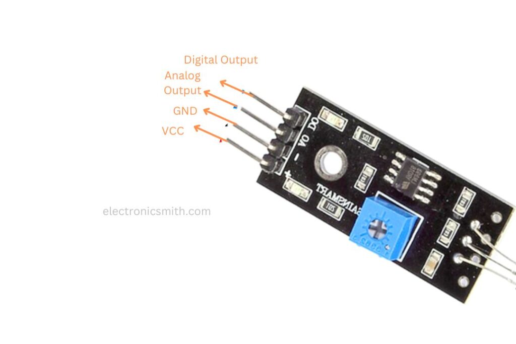
VCC Powers the module, often +5V, but also some modules will support 3.3V.
GND Ground connection for the power supply.
Digital Output Pin – directly tied to a digital input pin of a microcontroller. It goes HIGH or LOW depending on the availability of a magnetic field.
Analog Output Pin – tied to an analog input pin of a microcontroller, delivering variable voltage depending on the intensity of the detected magnetic field.
Schematics
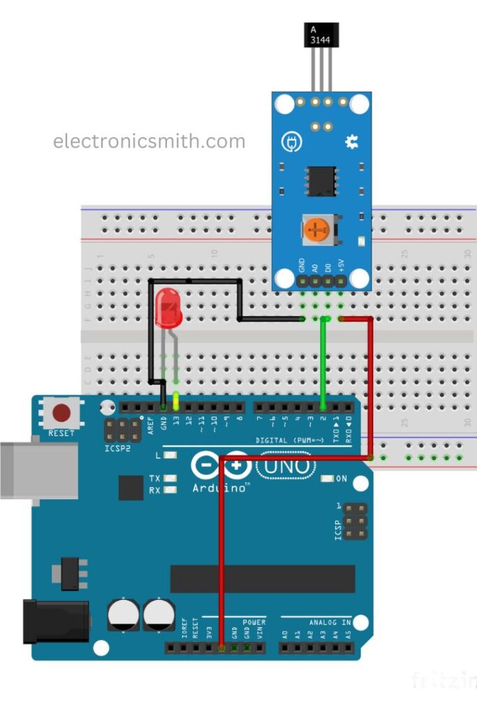
The circuit design of this project is easy. The Hall sensor’s three pins and an LED will be connected to the Arduino as given below:
Hall Sensor to Arduino:
VCC to 5V
GND → GND
SIG → D2
The LED is attached directly to pin 13 of Arduino with the positive leg in pin 13 and the negative leg in GND. No resistor is required since pin 13 has an internal resistor.
Code
int hallSensorPin = 2;
int ledPin =  13;
int state = 0;
void setup() {
  pinMode(ledPin, OUTPUT);
  pinMode(hallSensorPin, INPUT);
}
void loop(){
  state = digitalRead(hallSensorPin);
  if (state == LOW) {
    digitalWrite(ledPin, HIGH);
  } else {
    digitalWrite(ledPin, LOW);
  }
}
Conclusion:
Load the code into your Arduino board. When you bring the magnet near the sensor, the LED will turn on. When you remove the magnet, it will turn off.
Note: Some Hall effect sensors are reverse-acting, turning HIGH when they sense a magnetic field. Always refer to the sensor’s datasheet for proper configuration.