The Arduino Leonardo is one of the best boards provided by the Arduino platform.
It comes with the ATmega32u4 controller that has built-in USB support.
The Arduino Leonardo contains everything that is needed to support the microcontrollers just connect it to a computer with a USB cable or power it with an AC-to-DC adapter or battery to get started. Arduino Leonardo is very much similar to Arduino UNO try Arduino Leonardo vs Uno comparison and comment down. There is a mini version of Arduino Leonardo available name Arduino, micro.
How does Arduino Leonardo work?
The ATmega32u4 is a high-performance, low-power AVR 8-bit microchip. It has 32 kilobytes of memory (of which 4 KB is used by the bootloader), 2.5 KB of SRAM, and 1 KB of EEPROM. Arduino Leonardo uses ATmega32u4 controllers for function.
Crystal Oscillator
The Crystal oscillator inside the board has a frequency of 16MHz, which generates the clock signal in the microcontroller. Its basic function is to provide basic timing and control to the board.
Specifications
The Arduino Leonardo specifications are as follows
| Microcontroller | ATmega32u4 |
| Operating Voltage | 5V |
| Input Voltage (Recommended) | 7-12V |
| Input Voltage (limits) | 6-20V |
| Digital I/O Pins | 20 |
| PWM Channels | 7 |
| Analog Input Channels | 12 |
| DC Current per I/O Pin | 40 mA |
| DC Current for 3.3V Pin | 50 mA |
| Flash Memory | 32 KB (of which 4 KB is taken by the bootloader) |
| SRAM | 2.5 KB (ATmega32u4) |
| EEPROM | 1 KB (ATmega32u4) |
| Clock Speed | 16 MHz |
| Length | 68.6 mm |
| Width | 53.3 mm |
| Weight | 20 g |
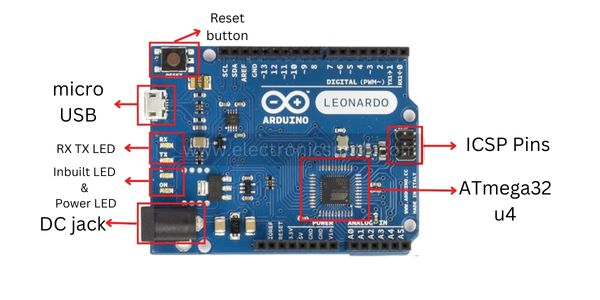
Arduino Leonardo Pinout

The Pinout diagram of Arduino Leonardo is given below
| Pin category | Representation | Description |
|---|---|---|
| Power pins | 5V, RESET, 3.3V, GND (3), Vin, AREF, IOREF | Pins used to deliver power to the device connected with Arduino |
| Digital pins | 0 to 13 | Pins used for digital input and outputs of Arduino |
| PWM pins | 13,11,10, 9, 6, 5, 3 | Pins used to generate the pulsating signal |
| Analog pins | A0 to A5 (A5 for SCL and A4 for SDA) | Pins used for analog inputs and outputs of Arduino |
| Miscellaneous pins | Additional pins for SCL and SDA | SCL is the clock pin, and the SDA is the data pin for I2C and TWI communication devices |
| 6 header pins | ICSP | Pins used to program the controller |
For communication purposes in Arduino Leonardo SCA and SDL, pins are given. We use pins A5 and A4 for the SCL and SDA respectively.
Arduino Leonardo IO pins
Digital Pins of the Arduino Leonardo
For connecting the digital devices with the Leonardo the Arduino has provided 14 pins from which Pin 0 and Pin 1 are used for transmitting and receiving of the data and are also called the communication pins.

As the word digital suggests it is associated with the data. According to this, the data will be in the form of 0 and 1.
For the generation of the input and output in the form of pulses, you can use pins 13,11,10, 9, 6, 5, and 3 of the Leonardo as they are dedicated pins of Pulse Width Modulation(PWM) and the duty cycle of the pulse is from 0 to 255.
Analog Pins of Arduino Leonardo:-
There are 6 Pins provided in Arduino Leonardo which are used to connect analog devices having resolutions ranging from 0 – 1024. In terms of voltage, it will be 5Volts for 1024.

The Arduino Leonardo has provided two dedicated pins next to the AREF pin which is used for the data line and clock of the I2C devices.
However, we can use pins A4 and A5 as the SDA and SCL pins respectively for the devices that used I2C and TWI (Two Wire Interface) communication protocols.
The SDA pin is the data line for the connected devices while SCL is the clock pin of the connected devices.
Power Pins Of Arduino Leonardo
There are three pins of ground are present, the first pin is for 5 volts, another pin is for 3.3 volts and the two pins are for giving the reference voltage for analog and digital devices.
There is also a reset pin available on the Arduino Leonardo board to RESET the Leonardo using an external button, however, a dedicated reset pin is provided on the Arduino Leonardo board.
For connecting the Arduino Leonardo board with the supply voltage there is one built-in USB port provided while for power supply purposes a jack is also provided.

The USB port can be used for power as well as to upload the code to the Arduino.
Arduino Leonardo Communication pins
ICSP header pins of the Arduino Leonardo
There are 6 header pins provided on the Arduino Leonardo board that is dedicated to in-circuit system programming (ICSP).

SPI Pins
SPI stands for Serial Peripheral Interface.
These pins are used by the microcontroller for communicating with one or more peripheral devices efficiently.
The Serial Peripheral Pins in Arduino Leonardo are present in the ICSP header, these pins SPI communication using SPI libraries.
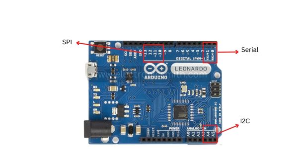
Two-Wire Interface (TWI)/I2C
I2C stands for Inter-Integrated Circuits. The I2C uses two lines to send and transmit data: a serial clock (SCL) pin and a serial data (SDA) pin.
Other Pins
AREF: Reference voltage for the analog inputs.
LED 13: In the board, there is a built-in LED connected to digital pin 13. When this pin is set to HIGH or 1, the LED is switched on, when this pin is set to LOW or 0, it’s switched off.
IOREF: This pin represents the voltage at which the I/O pins of the board are operating
Connection and Firmware of Arduino Leonardo
Connecting the device requires a USB data cable that is connected to a PC or a power supply from an external source.
For installing the Arduino Leonardo Driver
Following are the steps required to install the Arduino Leonardo driver:-
- connecting the device to the PC
- Waiting for the start of the software installation wizard (if there is no start, manually go to the hardware section, select the Arduino Leonardo line, and press update);
- searching for the drivers on the PC and clicking “Next”;
- In the folder with the software, select the required driver;
- accepting the installation.
For flashing the device, it is needed to press the Upload button to load the software into the memory of the device automatically.
Then, the controller’s reset is initiated, which leads to the bootloader start which is responsible for receiving, saving, and starting the new software. For elevated steps, you can refer to this article.
4 thoughts on “Grand 1 article on Arduino Leonardo Pinout and their functions read now”