Basically, a Tachometer is a device used to count on the number of rotations that the particular object is taking in the due time. Initially, the processing was all manual through mechanical coupling to count the rotations. Then, the RPM (revolutions per minute) is determined by the use of gear and displays the information on the dial.
But, with the up-gradation of technology, now, the tachometer can be made digital and contactless by using Arduino. Here, in this column, we’ll describe the making of a digital tachometer and let me tell you that it works on the principle of the motor speed and display the information on a 16*2 LCD screen.
Pre-requisites for Arduino Tachometer
- Arduino
- IR sensor Module
- 16×2 LCD
- Push-button
- Breadboard
- 9-volt battery
- Connecting wires
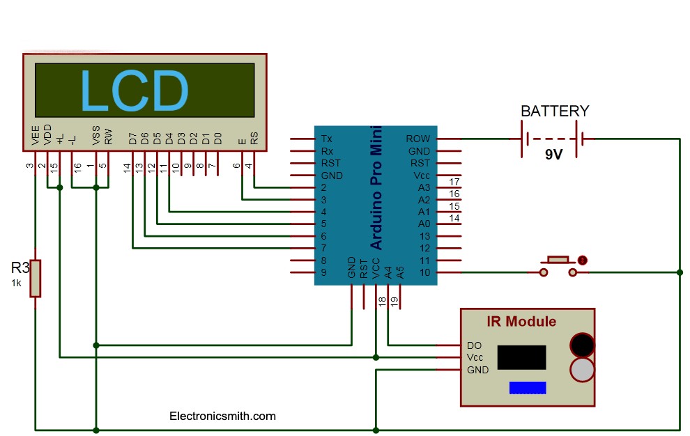
Connection diagram
RPM Sensor
The formation of the sensor is based on an IR phototransistor or IR LED. This transistor is responsive to the infra-red waves only and hence avoids other light interruptions happening in the environment. The alignment of the phototransistor and the IR diode is side by side and R2 resistor transmits the current through the IR diode.
We have used a 9 volts cooling fan for the process and make sure to have less than 1cm clearance between the sensor and the reflective strip. Now, the reflective strip crossed the sensor and reflected back the IR waves to the phototransistor, the resultant voltage comes to R3 i.e. 68k resister at the moment. It will form a wave kind of a structure and you can count the RPM by determining the upward shoots.
Count the RPM
We will use Arduino to count the RPM and let it display on the LCD screen, and connect the emitter of the phototransistor to the Interrupt 0 of the Arduino. This way, each upward shoot will be counted in an interrupt in the emitter waveform. The time elapsed during the counting cycle will be easily determined by using the millis function as this function identifies the number of milliseconds passed while the Arduino board is switching on. Then, calculate the difference with millis function by dividing the number of interruptions with milliseconds into 60000 will give you the RPM.
Controlling the Speed of Motor
Include a potentiometer to control the speed of the motor and transistor Q1 for driving the motor are essential. The base of Arduino is connected to PWM pin 9 via a limiting resistor R1. Wiper of the speed control POT R4 is connected to analog pin A0 of the Arduino. At this pin, the voltage will convert into a value between 0 to 1023 using an Analog write function.
Below, you can find out the program attached for a digital tachometer.
// Code for Arduino Tachometer
#include <LiquidCrystal.h>
LiquidCrystal lcd(3, 2, 4, 5, 6, 7);
#define sensor 18
#define start 10
int delay1()
{

    int i,j;
    unsigned int count=0;
    for(i=0;i<1000;i++)
    {
      for(j=0;j<1227;j++)
      {
       if(digitalRead(sensor))
       {
         count++;
         while(digitalRead(sensor));
       }
    }
  }
    return count;
}
void setup()
{
  pinMode(sensor, INPUT);
  pinMode(start, INPUT);
  pinMode(13, OUTPUT);
  lcd.begin(16, 2);
  lcd.print("Techometer");
  lcd.setCursor(0,1);
  lcd.print("Circuit Digest");
  delay(2000);
  digitalWrite(start, HIGH);
}
void loop()
{
     unsigned int time=0,RPM=0;
     lcd.clear();
     lcd.print("  Please Press  ");
     lcd.setCursor(0,1);
     lcd.print("Button to Start ");
     while(digitalRead(start));
     lcd.clear();
     lcd.print("Reading RPM.....");
     time=delay1();
     lcd.clear();
     lcd.print("Please Wait.....");
     RPM=(time*12)/3;
     delay(2000);
     lcd.clear();
     lcd.print("RPM=");
     lcd.print(RPM);
     delay(5000);
}
Check out more cool projects.
1 thought on “Arduino Tachometer”