About Arduino Pro Mini
Arduino Mini Pro is the smallest Arduino model available in the market. Here in this post, we’ll discuss about Arduino Pro Pinout and previously we have discussed about how to install Arduino IDE & How to upload the first code. Arduino Mini Pro Pinout‘s specification and programming will be discussed in this column.
This board is equally powerful as Arduino UNO, Mega, and Nano. Arduino Mini Pro is the smallest and lightest board. It is available in two variants Arduino Pro Mini 5V and Arduino Pro Mini 3.3V. First, we are going with Arduino Pro Mini Pinout and other features.
Buy Arduino mini with FTDI programer. https://amzn.to/3rurPl5
Specifications
Arduino Pro Mini has two variants 5v and 3.3v. The Arduino Pro Mini dimensions are 33×17 & 8. It does not have a USB connector and an FTDI programmer. Also, it has one reset button and an onboard voltage regulator. Almost every pin has an inbuild pull-up and pull-down resistors that can be initiate using the software.
| USB | × |
| Reset Button | ✓ |
| Voltage Regulator | ✓ |
| FTDI Programmer | × |
| Power LED | ✓ |
| Onboard LED | ✓ |
Micro-controller Specification
The micro-controller uses an Arduino Pro Mini 328 (Atmega 328p). It has 32K Bytes Flash Memory, 1K Bytes EEPROM, 2K Bytes internal RAM. Also, it has an 8Mhz clock frequency in the 3.3v variant and 16Mhz in the 5v variant.
| Flash Memory | 32KBytes |
| EEPROM | 1KBytes |
| Internal RAM | 2KBytes |
| 3.3v Clock Frequency | 8Mhz |
| 5v Clock Frequency | 16Mhz |
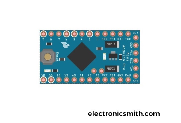
Arduino Pro Mini Pinout
Arduino Pro Mini has almost the same pins as Arduino Nano or UNO have. It has a total of 14 digital pins and 8 analog pins that supports serial communication, SPI, and UART protocols. It is a very simple pinout to be used.
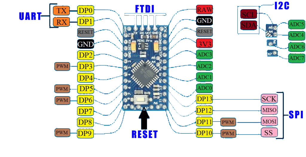
| Power Source | VCC, GND and VIN | VCC:- 5v or 3.3v GND:- GROUND VIN: Unregulated supply up to 12v |
| ADC | ADC-0,1,2,3,4,5,6,7 | Analog input |
| PWM | DP3, DP5, DP6, DP9, DP10, DP11 | These pins can provide Pulse width modulation output. |
| Reset | RESET | Reset the controller |
| Interrupts | T0 and T1 | Theses two pins for external hardware interrupts. |
| Analog Compararors | AIN0 and AIN1 | These two pins are connected to internal comparator. |
| Communication | UART SPI I2C | UART: DP0-TX, DP1-RX SPI: SCK-DP13, MISO -DP12, MOSI-DP11, SS-DP10 I2C: SCL-ADC5, SDA-ADC4 |

Programming
After discussing about the Arduino Pro Mini Pinout. The next question that comes to your mind is how to program Arduino Pro Mini. For doing that we need an FTDI programmer that uploads the code from the computer to Arduino Pro Mini 328p IC. FTDI programmer is not on the Arduino Mini Pro. So, we require an external FTDI programmer and need to connect it with the Arduino Mini. The connection is very simple, the diagram or table for your assistance.
| FTDI | Arduino Pro Mini |
| GND | BLK |
| CTS | GND |
| VCC | VCC |
| TX | RX |
| RX | TX |
| DTR | GND |

After completing the connection, open your Arduino IDE and go to Board>Select Arduino Mini. Verify and upload the code and select the correct port.

1 thought on “Arduino Pro Mini Pinout, Specification, and Programming”