
MPU6050 is a groundbreaking motion sensor that combines a 3-axis gyroscope and a 3-axis accelerometer in a single chip. This tiny engine enables precise detection of rotational motion and linear acceleration, making it ideal for applications ranging from drone stabilization to gesture-controlled devices. With its onboard Digital Motion Processor and I2C interface, the module simplifies motion tracking while offering customizable measurement ranges for different applications. Whether it is a self-balancing robot, VR controller, or fitness tracker, the MPU6050 delivers the precise motion data to make your project a reality. Its low power usage and compatibility with external sensors like magnetometers make it a universal choice for hobbyists and professional developers alike.
Materials Required:
| Component | Quantity |
|---|---|
| MPU6050 Module | 1 |
| Arduino Board (Uno/Nano) | 1 |
| Breadboard | 1 |
| Jumper Wires (M-M) | 4 |
| USB Cable (Type-A/B) | 1 |
Working of Accelerometer:
An accelerometer detects acceleration forces through a suspended microscopic mass that deflects when in motion. As the mass moves, it varies the capacitance between adjacent plates, which the sensor interprets as readable voltage signals. In MEMS accelerometers like the MPU6050’s, this entire mechanism is miniaturized onto a silicon chip. In static position, it detects gravity as a 1g force, enabling tilt sensing. When moving, it detects dynamic acceleration in three axes, enabling calculation of motion, vibration, and orientation. Its sensitivity is set by spring stiffness and mass size, with configurations for use in everything from fine gestures to high-impact shocks available, making it universal for use in mobile devices, through to car systems.
How a MEMS Accelerometer Works
A MEMS accelerometer detects acceleration through tiny silicon structures made on a chip. At the center is a tiny suspended proof mass suspended from compliant springs. During acceleration, inertia moves the mass away from its neutral position. This movement changes the capacitance between comb-shaped electrodes on the mass and fixed plates on the substrate.
The sensor measures these tiny capacitance changes and converts them into voltage signals that are proportional to acceleration. For detection in 3 axes (such as in the MPU6050), three separate MEMS structures detect X, Y, and Z motions. In stillness, it detects gravity as a static 1g acceleration, allowing for tilt detection. In motion, it detects dynamic forces for monitoring vibrations, shocks, or changes in orientation.
MEMS technology reduces this mechanical system down to one silicon chip via semiconductor processing, which makes it robust, energy-efficient, and usable in consumer electronics, automotive systems, and the Internet of Things. Having no conventional moving parts guarantees dependability after a million motion cycles.
Working of Gyroscope
A MEMS gyroscope works by utilizing the Coriolis effect on the microscopic level. Within the sensor, a minute silicon mass is made to vibrate incessantly back and forth at a precise frequency. The incessant vibration occurs in a particular plane, establishing the parameters to sense rotation.
Because the gyroscope is in angular motion, there is a fascinating phenomenon that takes place with the vibrating mass. The Coriolis effect is activated, generating a force that takes place at a right angle to the direction of vibration and the axis of rotation. This, in turn, generates a very slight deflection of the mass in another direction, a motion that would not take place without rotation.
The system detects such subtle displacements through changes in electrical capacitance. The dynamic mass is positioned between two stationary plates, and when it shifts due to rotation, the distance between these plates varies. These minuscule changes in capacitance are carefully measured and converted into electrical signals that precisely represent the rate of rotation.
In a device like the MPU6050, an on-chip three-axis gyroscope, multiple independent mechanisms for sensing collectively work to detect rotation in every direction. The various axes employ separate vibrating mass and sensing equipment so that the device can measure complicated motion consisting of rotation at numerous axes simultaneously.
As opposed to conventional mechanical gyroscopes that are comprised of a spinning wheel, MEMS gyroscopes are based on nanoscale vibrations in silicon. This new method makes them very small, resistant to vibration and shock, and suitable for mass production. Their small size and ruggedness have led to game-changing uses from smartphone motion sensors to sophisticated navigation systems in drones and space vehicles.
MPU6050 Module Overview

The MPU6050 module is built around a compact and efficient 6-axis motion tracking chip that combines a 3-axis gyroscope, 3-axis accelerometer, and a Digital Motion Processor (DMP) in a tiny 4mm × 4mm package. This integration allows it to measure both rotational movement (angular velocity) and linear acceleration, making it ideal for applications like drones, robotics, and motion-controlled devices.
The module includes an onboard 3.3V regulator, so it can be safely powered by a 5V microcontroller like an Arduino without risking damage. Power consumption is minimal—less than 3.6mA during active measurements and just 5μA in standby mode, making it suitable for battery-powered projects.
A small power LED indicates when the module is receiving voltage.
Measuring Acceleration
The MPU6050’s accelerometer can detect acceleration forces along the X, Y, and Z axes with programmable sensitivity ranges of ±2g, ±4g, ±8g, and ±16g. It uses three dedicated 16-bit analog-to-digital converters (ADCs) to sample each axis simultaneously, ensuring accurate and synchronized readings. This allows it to measure both static forces (like gravity for tilt sensing) and dynamic forces (such as vibrations or sudden movements).
Measuring Rotation
The gyroscope inside the MPU6050 tracks angular velocity (rotational speed) around the X, Y, and Z axes. It supports four selectable ranges: ±250°/s, ±500°/s, ±1000°/s, and ±2000°/s, making it adaptable for both subtle and rapid movements. Like the accelerometer, it uses three 16-bit ADCs for high-resolution data capture. The sampling rate can be adjusted from 3.9Hz up to 8kHz, depending on the application’s needs.
Temperature Sensing
An embedded temperature sensor provides readings from -40°C to 85°C with an accuracy of ±1°C. However, this sensor measures the internal temperature of the chip rather than the surrounding environment. While not ideal for ambient temperature monitoring, it helps compensate for thermal drift in the accelerometer and gyroscope, improving calibration accuracy over time.
I2C Interface
The MPU6050 communicates via the I2C protocol, supporting two configurable addresses: 0x68 (default) and 0x69. The AD0 pin controls the address selection—leave it unconnected (or ground it) for 0x68 or connect it to 3.3V for 0x69. This flexibility allows multiple MPU6050 modules to coexist on the same I2C bus or avoid conflicts with other sensors.
External Sensor Support
For enhanced functionality, the module provides auxiliary I2C pins (XDA and XCL) to connect external sensors, such as a magnetometer. While the MPU6050 alone offers 6 degrees of freedom (6DOF), adding a magnetometer enables 9DOF tracking by incorporating compass data. This is useful for applications requiring absolute orientation, like navigation systems or stabilized platforms.
Pinout:
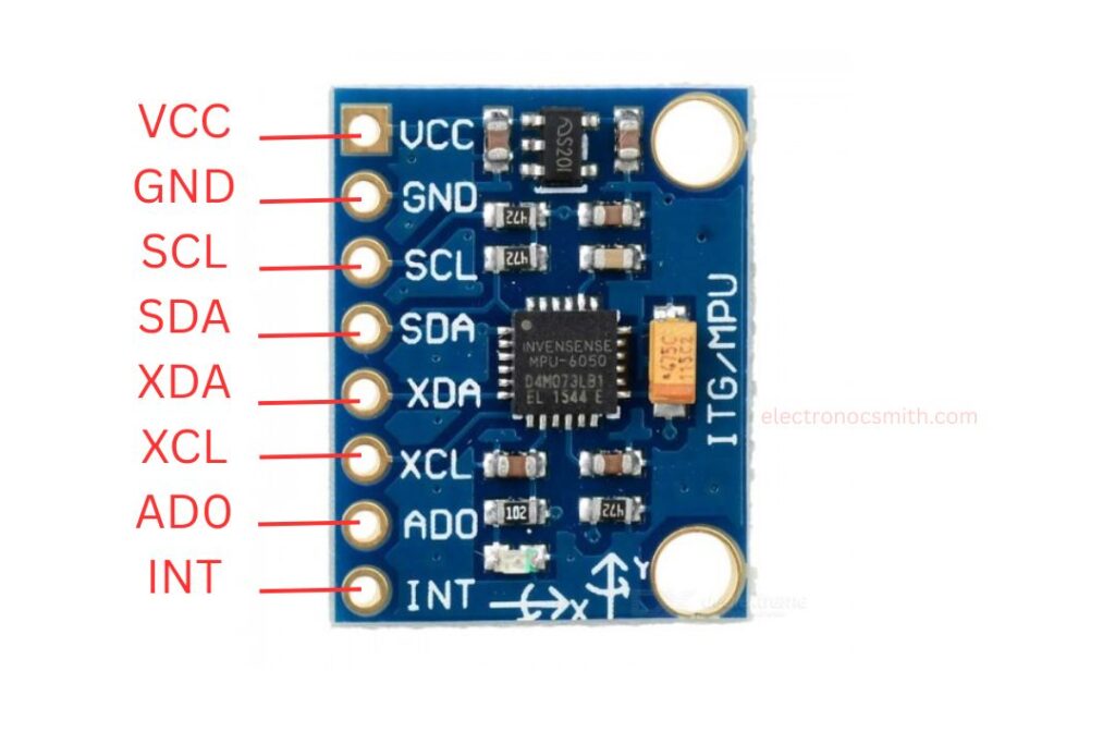
- VCC – Power supply (5V input, regulated to 3.3V internally).
- GND – Ground connection.
- SCL – I2C clock line.
- SDA – I2C data line.
- XDA – Auxiliary I2C data for external sensors.
- XCL – Auxiliary I2C clock for external sensors.
- AD0 – I2C address selection (LOW = 0x68, HIGH = 0x69).
- INT – Interrupt output for event detection (e.g., motion, taps).
Connecting to Arduino
Wiring the MPU6050 to an Arduino is simple:
- VCC → 5V
- GND → GND
- SCL → A5 (or the board’s SCL pin)
- SDA → A4 (or the board’s SDA pin)
Some Arduino models (like the Uno R3) label I2C pins as A4 (SDA) and A5 (SCL), while newer boards (e.g., Nano 33 IoT) have dedicated SDA/SCL pins. Always verify the pinout for your specific board.
Software Setup
To read sensor data easily, install the Adafruit MPU6050 library via the Arduino IDE’s Library Manager. This library simplifies accessing raw accelerometer, gyroscope, and temperature readings. Additionally, install the required dependencies:
- Adafruit Unified Sensor (for standardized data handling)
- Adafruit Bus IO (for I2C communication)
Once installed, example sketches can be used to test the module and start integrating motion tracking into projects.
Arduino Code Examples
Basic Reading
#include <Adafruit_MPU6050.h>
#include <Adafruit_Sensor.h>
#include <Wire.h>

Adafruit_MPU6050 mpu;

void setup() {
  Serial.begin(115200);
  if (!mpu.begin()) {
    Serial.println("MPU6050 not found!");
    while (1);
  }
  mpu.setAccelerometerRange(MPU6050_RANGE_8_G);
  mpu.setGyroRange(MPU6050_RANGE_500_DEG);
  mpu.setFilterBandwidth(MPU6050_BAND_21_HZ);
}

void loop() {
  sensors_event_t a, g, temp;
  mpu.getEvent(&a, &g, &temp);

  Serial.print("Accel X: "); Serial.print(a.acceleration.x);
  Serial.print(", Y: "); Serial.print(a.acceleration.y);
  Serial.print(", Z: "); Serial.print(a.acceleration.z); Serial.println(" m/s²");

  Serial.print("Gyro X: "); Serial.print(g.gyro.x);
  Serial.print(", Y: "); Serial.print(g.gyro.y);
  Serial.print(", Z: "); Serial.print(g.gyro.z); Serial.println(" rad/s");

  Serial.print("Temp: "); Serial.print(temp.temperature); Serial.println(" °C");
  delay(500);
}
Serial Plotter Visualization
void loop() {
  sensors_event_t a, g, temp;
  mpu.getEvent(&a, &g, &temp);

  Serial.print(a.acceleration.x); Serial.print(",");
  Serial.print(a.acceleration.y); Serial.print(",");
  Serial.print(a.acceleration.z); Serial.print(",");
  Serial.print(g.gyro.x); Serial.print(",");
  Serial.print(g.gyro.y); Serial.print(",");
  Serial.println(g.gyro.z);
  delay(10);
}
Conclusion
The MPU6050 revolutionizes motion sensing with its single-chip 6-axis solution, packing professional-grade gyroscopic and accelerometer capability into a fingernail-sized package. This gem provides accurate real-time orientation data while conserving power, making it ideal for everything from smartphone motion control to autonomous drone flight. Its onboard processing handles the heavy math, leaving your main microcontroller free for other duties. With plug-and-play ease but also sophisticated customization options, the MPU6050 puts space-age motion tracking technology into the makers’ and engineers’ hands, and opens the door to innovative applications we’re only just starting to discover. The revolutionary impact of this small chip continues to revolutionize the way machines interact with the physical world.