
The Arduino Nano Every is the evolved version of the Arduino Nano Board.
The Nano Every Board is the smallest board in the Arduino family with dimensions of 45x18mm and a weight under 5 grams. The low price and small size of this board make it an ideal pick for the range of electrical projects like electronic musical instruments, low-cost robots, and the general development of the small parts of large projects.
As compared to Arduino Nano Board, is a tiny powerful board that is based on the ATMega4809 AVR processor and has Random Access Memory(RAM) three times more than the Arduino nano.
The Arduino Nano Every has 2 variants:-
- One With header
- One Without header
Arduino Nano Every Board Layout
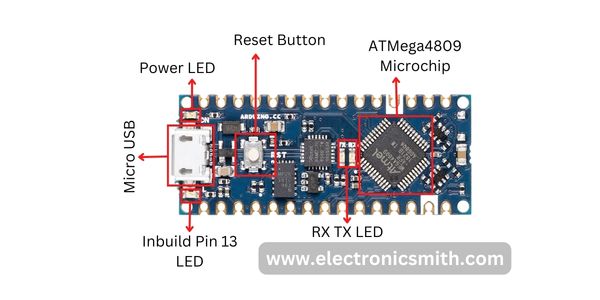
ATMega4809 Microchip
It is an 8-bit AVL processor developed by Atmel. The ATMega4809 can run up to 20MHz.
It has 6 Kilobytes of SRAM, 48KB of flash, and 256 bytes of EEPROM.
The ATMega4809 chip consists of the latest features like efficient and flexible-power architecture, including Event System, Sleepwalking, precious analog features, and advanced peripherals.
Micro USB Port
The Nano Every consists of a Micro USB port while in Nano it has a Mini USB B port. This micro USB board is used to power up the Nano Every board as well as to connect with a computer for flashing the code.
RESET Button
The Nano Every board comes with a RESET button which is used to reset the board and begin the execution of the program from the beginning.
Power LED
The board consists of a LED that will light up when the board is connected to the computer or to the power supply.
IN-Built LED(13)
An IN-Built LED is connected to pin number 13 on the board which can be controlled by switching the pin to high or low.
RX and TX LED
The Arduino Nano Every board consists of an RX and a TX LED which will light up whenever a receiving or transmitting of data takes place.
These two LEDs are connected to the UART pin RX(1) and TX(0) respectively.
Specifications of Arduino Nano Every
The specifications of Arduino Nano Every are shown in the table below
| MCU | ATmega4809 |
| Architecture | AVR |
| Operating Voltage | 5V |
| Input Voltage | 7V – 12V |
| DC Current per I/O | 15mA |
| Clock Speed | 16 MHz |
| Flash Memory | 32 KB (2 KB of this used by bootloader) |
| SRAM | 2 KB |
| EEPROM | 1 KB |
| Digital IO Pins | 22 (of which 6 can produce PWM) |
| Analog Input Pins | 8 |
| PWM Pins | 5 |
| Built-in LED | 13 |
| Weight | 5gr |
| Width | 18 mm |
| Length | 45 mm |
These are the specifications of Arduino Nano Every.
Arduino Nano Every Pinout

| Pin Number | Pin Name | Description | Alternative Functions |
| 1 | TX / D1 | Digital IO Pin 1Serial TX Pin | Generally used as TX |
| 2 | RX / D0 | Digital IO Pin 0Serial RX Pin | Generally used as RX |
| 3 | RST | Reset (Active LOW) | |
| 4 | GND | Ground | |
| 5 | D2 | Digital IO Pin 2 | |
| 6 | D3 | Digital IO Pin 3 | Timer (OC2B) |
| 7 | D4 | Digital IO Pin 4 | Timer (T0/XCK) |
| 8 | D5 | Digital IO Pin 5 | Timer (OC0B/T1) |
| 9 | D6 | Digital IO Pin 6 | |
| 10 | D7 | Digital IO Pin 7 | |
| 11 | D8 | Digital IO Pin 8 | Timer (CLK0/ICP1) |
| 12 | D9 | Digital IO Pin 9 | Timer (OC1A) |
| 13 | D10 | Digital IO Pin 10 | Timer (OC1B) |
| 14 | D11 | Digital IO Pin 11 | SPI (MOSI) Timer (OC2A) |
| 15 | D12 | Digital IO Pin 12 | SPI (MISO) |
| 16 | D13 | Digital IO Pin 13 | SPI (SCK) |
| 17 | D14 | Digital IO Pin 14 | |
| 18 | D15 | Digital IO Pin 15 | |
| 19 | D16 | Digital IO Pin 16 | |
| 20 | D17 | Digital IO Pin 17 | |
| 21 | D18 | Digital IO Pin 18 | |
| 22 | D19 | Digital IO Pin 19 | |
| 23 | D20 | Digital IO Pin 20 | |
| 24 | 3V3 | Power | |
| 25 | AREF | Analog Reference | |
| 26 | A0 | Analog Input 0 | |
| 27 | A1 | Analog Input 1 | |
| 28 | A2 | Analog Input 2 | |
| 29 | A3 | Analog Input 3 | |
| 30 | A4 | Analog Input 4 | I2C (SDA) |
| 31 | A5 | Analog Input 5 | I2C (SCL) |
| 32 | A6 | Analog Input 6 | |
| 33 | A7 | Analog Input 7 | |
| 34 | 5V | +5V Output from regulator or +5V regulated Input |
The Arduino Nano Every board consists of 30 pins in total out of which 20 pins are digital input/output pins. From these 20 pins, 5 are Pulse Width Modulation(PWM) pins and 8 are analog pins. A reset button.
The pinout of Arduino Nano Every is discussed below.
Power Pins
Vin
The Vin pin is used as a voltage input pin which powers up the Arduino board. Once a certain amount of voltage is given to the board with the help of a micro USB port to power the board, this voltage also shows up at the Vin pin.
3v3 Pin
The 3v3 pin is used to generate the output voltage of 3 volts.
5v
The 5v pin is used to generate regulated 5 volts outputs for the externally connected components. The power source of the 5v pin for the Arduino Nano Every board is the USB connector and Vin pin.
GND
The GND pin is used as a ground pin. There are two ground pins available on Arduino Nano Every Board.
Digital Pins
There are a total of 20 Input/Output pins present on Arduino Nano Every board can be used as an input or output. These pis operate at 5 volts.
These I/O pins can read only two states i.e, when current is present and when current is absent. When current is present it is referred to as High(1) and when current is absent it is referred to as Low(0).
PWM pins
PWM stands for Pulse Width Modulation. There are five PWM pins present on Arduino Nano on Every board which are 3,5,6,9 and 10.
These pins are used for converting digital signals into analog signals.
Each PWM pin produces 8 – bit PWM output. To generate the PWM output we have to use the syntax “analog write (PWM Pin, PWM value)”. PWM values vary between 0 volts to 255 volts.
Analog Pins
The number of Analog Pins incorporated on Arduino Nano Every board is 8 labeled as AX where x is the pin number. All of the analog pins can also be utilized as digital I/O pins. The analog pins can receive any number of values while the digital pins only receive two values i.e, High or Low.
Communication Pins Of Arduino Nano Every
I2C Pins
I2C is the two-wire serial communication protocol. The I2C protocol uses two pins for sending and receiving serial data as well as clock data. The two pins are the Serial clock pin(SCL) A5 and the Serial data pin(SDA) A4.
- SCL pin(Pin A5):- It stands for Serial Clock pin. This pin is used for sending clock data between the devices. This pin is also used for synchronization purposes. The SCL pin is provided by the master device. It is also known as the Clock Line.
- SDA pin(Pin A4):- It stands for Serial data pin. This pin is used for both sending and receiving the data and this is the reason behind its name “Data Line”.
This pin is operated by both master and slave devices.
SPI Pins
SPI stands for “Serial Peripheral Interface”. These pins are mainly used to carry out the communication between the microcontroller and the other peripheral devices such as sensors or shift registers efficiently and effectively.
The Arduino Nano Every board consists of 4 SPI Pins:-
- SCK (Serial Clock) D13
- SS (Slave Select) D8
- MOSI (Master Output Slave Input) D11
- MISO (Master Input Slave Output) D12
The pins MOSI and MISO are employed to receive or send data by the microcontroller.
UART Pins
These pins are used for serial communication. It carries two lines TX and RX. 0(RX) is used to receive data and 1(TX) to transmit (TX) TTL serial data using the ATMega4809 Microprocessor’s advanced hardware serial capabilities.
Programming of Arduino Nano Every Board
- Arduino Integrated Development Environment (IDE) is used to program the Nano Every board.
- Arduino IDE contains a built-in bootloader used to install the program inside the Microcontroller.
- The Arduino Nano Every Board consists of a micro USB port which is used to connect the device to the computer. By using this Micro USB port, you can test and run the program directly from the computer.
Frequently Asked Questions:-
1) What can an Arduino Nano Every do?
Arduino Nano Every is suitable for making wearable inventions, low-cost robotics, and interactive projects. It is also used to create electronic musical instruments and is generally used to control smaller parts of larger projects.
2) Does Arduino Nano Every have WiFi?
No, Arduino Nano, Everyone does not have Wi-Fi or Bluetooth features.
3) Difference between Arduino Nano and Arduino Nano Every?
The Arduino Nano Every is a pin equivalent and evolved version of the Arduino Nano. As compared to the Nano’s ATmega328p processor and 2 KB of RAM, Nano every comes with a powerful processor ATmega4809 (20Mhz) and 3 times larger RAM capacity of 6 KB than Arduino Nano for more details download the datasheet.
4) What are the actual voltage thresholds for digital I/O?
The voltage threshold for I/O pins is 0.5+VCC. So if VCC is 5V then the absolute max is 5.5V as an input.