
We usually see electronic weighing machines in stores that display weight instantly when an object is placed on the weighing scale. Here, we are going to make a similar weighing machine using an Arduino and a Load Cell that can measure up to 40kg. If needed, it can be increased by using a Load Cell with higher capacity. Load Cell and HX711 Sensor Explained
Materials Required:
| Component | Quantity |
|---|---|
| Arduino Uno | 1 |
| Load Cell (40kg) | 1 |
| HX711 Load Cell Amplifier Module | 1 |
| 16×2 LCD Display | 1 |
| Connecting Wires | As needed |
| USB Cable | 1 |
| Breadboard | 1 |
| Nuts, Bolts, Frame, and Base | As needed |
Working
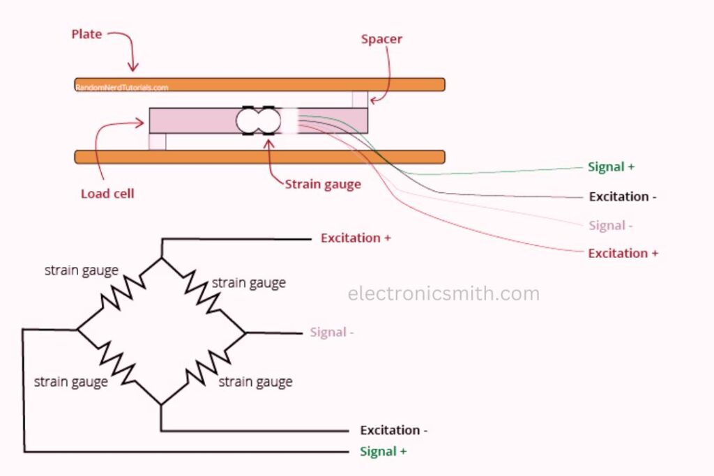
Strain gauge load cells are made of a metal bar with strain gauges affixed (tucked away beneath the white glue in the above picture). A strain gauge is an electrical sensor that measures force or strain on an object. When a force is applied to the object (in this instance, the metal bar), the object deforms, which alters the resistance of the strain gauge. This resistance change is proportional to the applied load, allowing us to determine an object’s weight. Normally, load cells have four strain gauges set up in a Wheatstone bridge configuration (illustrated below) to allow accurate resistance measurements. The electrical signals produced by the load cell, however, are mere millivolts and hence must be amplified prior to further processing. The HX711 Weighing Sensor Module does this job.
The HX711 module includes an HX711 chip, a 24-bit high-precision analog-to-digital converter. It includes two channels of analog input and provides gain settings of up to 128 through programming. The module takes the low electrical output from the load cell, converts it into digital, and then sends it to an Arduino to measure weight.
Hardware Overview:
HX711 is a small and high-precision 24 bit analog to digital converter that was designed for applications in weighing scales and industrial equipment. It is generally used for interfacing load cells with microcontrollers like Arduino, Raspberry Pi, and ESP8266 for weighing. This module is small and therefore can be conveniently used in a broad variety of projects. It has an onboard low-noise programmable gain amplifier (PGA) that allows small voltage signals from the load cell to be accurately converted into digital data.
Pinout:
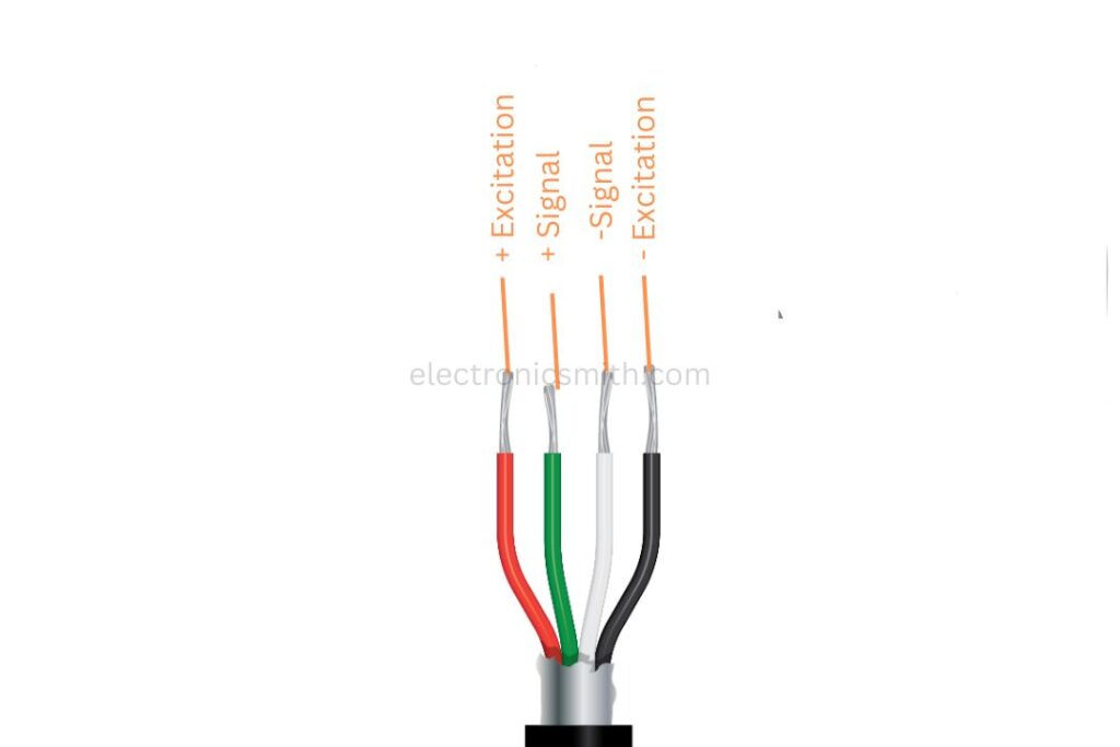
The load cell wiring consists of four primary wires, each with a specific function:
- Red – Excitation+ (E+), connected to the E+ pin on the HX711.
- Black – Excitation- (E-), connected to the E- pin.
- White – Signal+ (A+), connected to the A+ pin.
- Green – Signal- (A-), connected to the A- pin.
There are certain load cells with a shield wire, typically yellow or grey, which need to be connected to GND to minimize interference. The working of a load cell is straightforward. When weight is applied, the internal strain gauges are slightly stretched, causing a small change in resistance. This alteration alters the bridge voltage, which is amplified and converted into a digital signal by the HX711 module. This information is then calculated by a microcontroller such as an Arduino or ESP32 to calculate the weight.
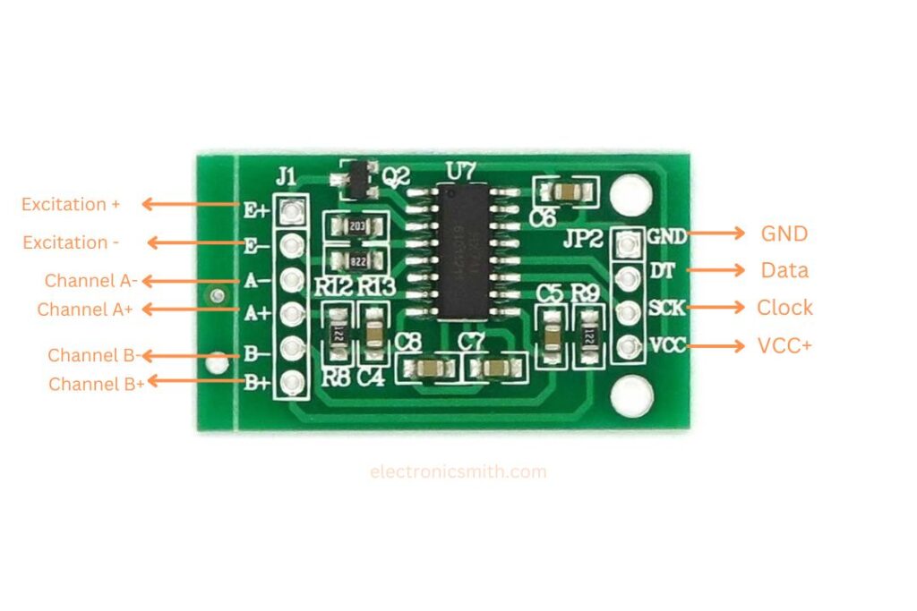
VCC – Power voltage (2.7V – 5V, usually 5V in the case of Arduino)
GND – Common
DT – (Data Output) – Transmits digital weight value to the microcontroller
E+ – (Excitation Positive) – Connects to the Red wire of load cell
E- – (Excitation Negative) – Connects to the Black wire of the load cell
A+ – (Input Channel A Positive) – Goes to the White wire of the load cell
A- – (Input Channel A Negative) – Goes to the Green/Blue wire of the load cell
Channel A: 128 or 64 programmable gain (widely used)
Channel B: Fixed 32 gain
Connection:
The load cell is connected to the HX711 Load Cell Amplifier through four wires, although wire colors can be marginally different across modules. Here are the conventional connections:
RED wire → E+
BLACK wire → E-
WHITE wire → A-
GREEN/BLUE wire → A+
In this configuration, the signal can be efficiently processed, allowing one to measure weight accurately through the use of an Arduino or similar microcontrollers.
Mounting the Load Cell with a Platform and Base
For accurate measurement of weights, we must install the Load Cell on a base and a platform to put things on. Even though you can simply weigh things directly on the Load Cell, a platform will give it stability. We use a wooden board as the base and a solid cardboard as a platform to put things on in our project. We install the Load Cell on the base using nuts and bolts.
Circuit Diagram and Description
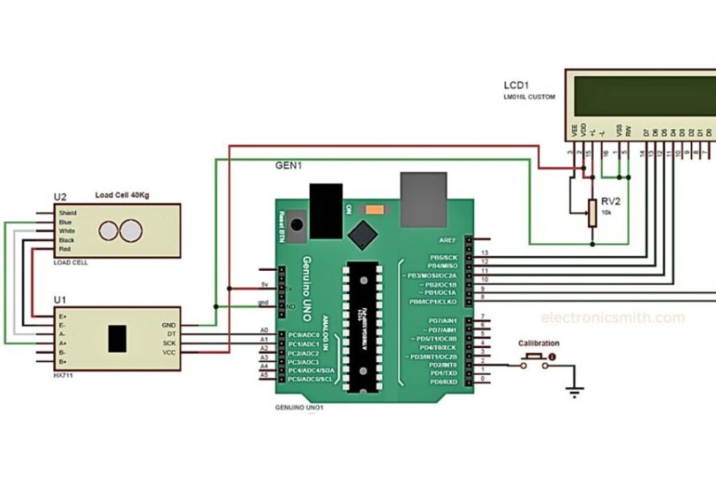
The circuit is straightforward:
16×2 LCD is interfaced with Arduino as follows: RS, EN, D4, D5, D6, and D7 are interfaced with pins 8, 9, 10, 11, 12, and 13 respectively.
The SCK and DT pins of the HX711 module are wired to Arduino pins A1 and A0.
The Load Cell is wired to the HX711 module as outlined.
How it works
The system auto-calibrates during start-up. To be manually calibrated, a pushbutton is utilized. Arduino accepts the HX711’s signal, converts it into weight, and puts the amount read into LCD display.
Calibration Procedure
Prior to weighing, the system has to be calibrated:
1. At startup, the LCD tells the user to place a 100g weight on the Load Cell.
2. The system maintains this reference weight and responds accordingly.
3. Once calibrated, the system is able to measure 40kg with precision.
Codes:
This code controls the entire process. It reads the values from the HX711 module, computes it, and displays the weight on the LCD. copy the code and upload it to Arduino.
#include <LiquidCrystal.h>
LiquidCrystal lcd(8, 9, 10, 11, 12, 13);

#define DT A0
#define SCK A1
#define sw 2

long sample = 0;
float val = 0;
long count = 0;

unsigned long readCount(void) {
  unsigned long Count;
  unsigned char i;
  pinMode(DT, OUTPUT);
  digitalWrite(DT, HIGH);
  digitalWrite(SCK, LOW);
  Count = 0;
  pinMode(DT, INPUT);
  while (digitalRead(DT));
  for (i = 0; i < 24; i++) {
    digitalWrite(SCK, HIGH);
    Count = Count << 1;
    digitalWrite(SCK, LOW);
    if (digitalRead(DT)) Count++;
  }
  digitalWrite(SCK, HIGH);
  Count = Count ^ 0x800000;
  digitalWrite(SCK, LOW);
  return (Count);
}

void setup() {
  Serial.begin(9600);
  pinMode(SCK, OUTPUT);
  pinMode(sw, INPUT_PULLUP);
  lcd.begin(16, 2);
  lcd.print("    Weight ");
  lcd.setCursor(0, 1);
  lcd.print(" Measurement ");
  delay(1000);
  lcd.clear();
  calibrate();
}

void loop() {
  count = readCount();
  int w = (((count - sample) / val) - 2 * ((count - sample) / val));
  Serial.print("weight: ");
  Serial.print((int)w);
  Serial.println(" g");
  lcd.setCursor(0, 0);
  lcd.print("Weight ");
  lcd.setCursor(0, 1);
  lcd.print(w);
  lcd.print(" g");

  if (digitalRead(sw) == 0) {
    val = 0;
    sample = 0;
    w = 0;
    count = 0;
    calibrate();
  }
}

void calibrate() {
  lcd.clear();
  lcd.print("Calibrating...");
  lcd.setCursor(0, 1);
  lcd.print("Please Wait...");
  for (int i = 0; i < 100; i++) {
    count = readCount();
    sample += count;
    Serial.println(count);
  }
  sample /= 100;
  val = (readCount() - sample) / 100.0;
  lcd.clear();
  lcd.print("Calibration Done");
  delay(1000);
  lcd.clear();
}
Conclusion:
In this project, we interfaced a Load Cell and an HX711 module with an Arduino to create a simple but effective weighing scale. This system can be enhanced with additional features like an automatic tare, wireless communication, or compatibility with other systems.