As the name indicates, the line follower robot is a computerized vehicle that tracks a visual line marked on the surface. This visual line is a route on which the line-follower robot travels. Typically, it tracks a black line on a white surface, or you can modify it as a white line on a black surface. Students and starters receive their first taste of robotics using this kind of robot. In this project-oriented article, we show you how to create a line follower robot based on Arduino. Line follower robots are applied in order to help the automatic manufacturing process. They are utilized in military missions, human supporting functions, delivery operations, etc.
Materials Required
| Component | Quantity | Description |
|---|---|---|
| Arduino Uno | 1 | Microcontroller board |
| IR sensor | 2 | For detecting black and white surfaces |
| L293D motor driver | 1 | For controlling the motors |
| BO motor | 4 | To drive the robot |
| Wheels | 4 | For movement |
| Lithium-ion battery | 1 | Power source |
| Jumper cables | Several | For connections |
| Robot chassis | 1 | Base for mounting components (or use cardboard) |
Workings:
The idea of the line follower robot is connected to light. In this case, we are utilizing the way light behaves on white and black surfaces. The white surface reflects all the light that comes into contact with it, while the black surface absorbs the light. Here, in this line-follower robot, we have employed IR transmitters and receivers (photodiodes). They transmit and receive light. If IR rays come on a white surface and then they get reflected towards the IR receiver, causing voltage changes.
Black surfaces are infrared absorbers and do not reflect any of the rays that hit them, and therefore no photons are received by the infrared receiver. In constructing this if the IR sensor detects a white surface, the Arduino receives 1 (high) as input. If it detects a black line, the Arduino receives 0 (low) as input. Depending on these inputs, the Arduino Uno gives the correct output to drive the bot.
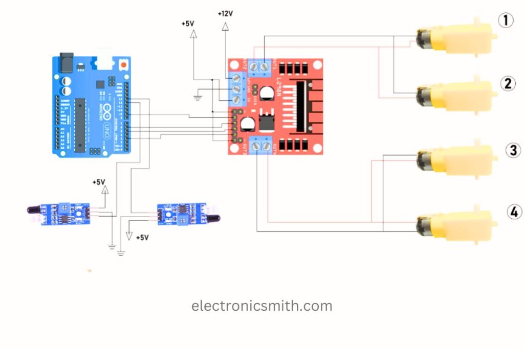
Line Follower Robot Connection Diagram:
We have employed four BO motors here. Motors 1 and 2 are linked to channel 1 of the L298N motor driver, and motors 3 and 4 are linked to channel 2 of the motor driver.
IN1, IN2, IN3, and IN4 are wired to Arduino Uno pins 9, 6, 5, and 3. +5V and the enable pins (EN1 and EN2) are joined by a jumper. It can be disconnected and an external connection made as indicated in the diagram.
Software & Programming Code for Line Follower Robot:
Download the Arduino IDE software and upload the code to your board. Final Output
int mot1 = 9;
int mot2 = 6;
int mot3 = 5;
int mot4 = 3;

int left = 13;
int right = 12;

int Left = 0;
int Right = 0;

void LEFT(void);
void RIGHT(void);
void STOP(void);

void setup() {
  pinMode(mot1, OUTPUT);
  pinMode(mot2, OUTPUT);
  pinMode(mot3, OUTPUT);
  pinMode(mot4, OUTPUT);

  pinMode(left, INPUT);
  pinMode(right, INPUT);

  digitalWrite(left, HIGH);
  digitalWrite(right, HIGH);
}

void loop() {
  analogWrite(mot1, 255);
  analogWrite(mot2, 0);
  analogWrite(mot3, 255);
  analogWrite(mot4, 0);

  while (1) {
    Left = digitalRead(left);
    Right = digitalRead(right);

    if ((Left == 0 && Right == 1) == 1)
      LEFT();
    else if ((Right == 0 && Left == 1) == 1)
      RIGHT();
  }
}

void LEFT(void) {
  analogWrite(mot3, 0);
  analogWrite(mot4, 30);

  while (Left == 0) {
    Left = digitalRead(left);
    Right = digitalRead(right);
    if (Right == 0) {
      int lprev = Left;
      int rprev = Right;
      STOP();
      while (((lprev == Left) && (rprev == Right)) == 1) {
        Left = digitalRead(left);
        Right = digitalRead(right);
      }
    }
    analogWrite(mot1, 255);
    analogWrite(mot2, 0);
  }
  analogWrite(mot3, 255);
  analogWrite(mot4, 0);
}

void RIGHT(void) {
  analogWrite(mot1, 0);
  analogWrite(mot2, 30);

  while (Right == 0) {
    Left = digitalRead(left);
    Right = digitalRead(right);
    if (Left == 0) {
      int lprev = Left;
      int rprev = Right;
      STOP();
      while (((lprev == Left) && (rprev == Right)) == 1) {
        Left = digitalRead(left);
        Right = digitalRead(right);
      }
    }
    analogWrite(mot3, 255);
    analogWrite(mot4, 0);
  }
  analogWrite(mot1, 255);
  analogWrite(mot2, 0);
}

void STOP(void) {
  analogWrite(mot1, 0);
  analogWrite(mot2, 0);
  analogWrite(mot3, 0);
  analogWrite(mot4, 0);
}
Final Output:
Once the code is uploaded, if your bot is not moving in the correct direction, then modify the BO motor wiring. Also, calibrate the IR sensors by adjusting their potentiometers.