Time is vital in the modern world, and timing is crucial when it comes to some devices because they, too, need a mechanism to keep track of time. Thus, how do electronics operate? The Real-Time Clock also called an RTC or DS3231, is a timekeeping device integrated into an Integrated Circuit or IC. Much time-sensitive software and hardware, including servers, GPS, and data loggers, use it. We’ll examine what makes it TICK.
Features of DS3231 Module
The DS3231 is an incredibly accurate and reasonably priced I2C real-time clock with an integrated temperature-compensated crystal oscillator. The system features a battery input and can continue to retain accurate time even if the module’s power is cut off. The addition of the crystal oscillator enhances the long-term accuracy of the instrument. The RTC records seconds, minutes, hours, days, dates, months, and years.
The date at the end of the month, including leap year corrections, is automatically changed for months with fewer than 31 days. The clock displays AM/PM and can operate in 12- or 24-hour modes. Along with programmable square-wave output, there are two programmable time-of-day alarms provided. Address and data are serially transported using an I2C bidirectional bus.
How DS3231 RTC Module works
DS3231 RTC chip
Information about the seconds, minutes, hours, day, date, month, and year is stored in the RTC chip. For months with fewer than 31 days, including leap year corrections, the date is automatically altered to come after the month. This board’s SQW pin, which is programmatically controllable, produces a gorgeous square wave at a frequency of 1Hz, 4kHz, 8kHz, or 32kHz. In many time-based applications, this can also be used as an interrupt due to an alarm.

Temperature Compensated Crystal Oscillator(TCXO)
RTC modules come with an external 32kHz crystal for keeping time. The problem with these crystals is that the temperature outside can affect how frequently they oscillate. Although the frequency variation might not seem like much, it affects the overall result.
To avoid such tiny crystal drifts, the DS3231 is operated by a 32kHz temperature-adjusted crystal oscillator. It can withstand changes in the outside temperature pretty well. The TCXO is fitted inside the RTC chip, which makes the whole box big. The temperature sensor is fitted near the crystal to overview the overall temperature.
To maintain precise timekeeping, this sensor adds or subtracts ticks from the clock to account for frequency variances.
This sensor adds or subtracts clock ticks to account for frequency variations to maintain accurate timekeeping.
Battery Backup
The bottom side of the board holds a battery holder for 20mm 3V lithium coin cells. Any CR2032 battery can fit well. Assuming a fully charged CR2032 battery with a capacity 220mAh is used and the chip consumes its minimum of 3µA, the battery can keep the RTC running for a minimum of 8 years without an external 5V power supply.

Onboard 24C32 EEPROM
A 32-byte Atmel 24C32 EEPROM chip with unlimited read-write cycles is also included with the DS3231 RTC module. It can be used for practically anything, including saving settings. Sharing an I2C bus with the DS3231, The 24C32 EEPROM communicates through the I2C interface.
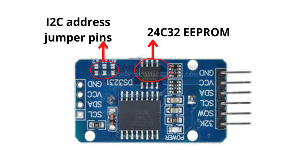
The three A0, A1, and A2 solder jumpers on the back make modifying the EEPROM’s I2C address simple. The addresses are hardcoded into each of these. Soldering a jumper short establishes the address.
As per the 24C32’s datasheet, these 3 bits are placed at the end of the 7-bit I2C address, just before the Read/Write bit.
As there are 3 address inputs, which can take 2 states, either HIGH/LOW, we can therefore create 8 (23) different combinations(addresses).
By shorting the solder jumpers, the address inputs are pulled LOW. It allows you to set the I2C address according to the below table.

By default, all the 3 address inputs are pulled HIGH using onboard pull-ups, giving 24C32 a default I2C address of 1010111Binary or 0x57Hex.
DS3231 RTC Module Pinout
The DS3231 RTC module interfaces with the outside world using a total of 6 pins. The relationships are as follows:
33k A reliable and accurate reference clock is output through the 32K pin and is temperature adjusted.
SQW pin may be controlled programmatically and produces a lovely square wave at 1Hz, 4kHz, 8kHz, or 32kHz. In many time-based applications, this can also be used as an interrupt due to an alarm.
SCL pin is a serial clock pin for the I2C interface.
SDA is an I2C interface pin for serial data.
VCC pin powers the module. It can be any voltage between 3.3 and 5.5 volts.
GND A ground pin is designated as GND.
Material required
The following supplies are required for this tutorial:-
| Name | Quantity |
| Arduino UNO | 1 |
| DS3231 module | 1 |
| Jumper wires | as per requirement |
| Oled display | 1 |
Circuit connection
Connections are reasonably easy. The VCC pin should first be connected to the Arduino’s 5V output, and GND should be connected to the Arduino GND.

We are still working on the pins that are utilized for I2C communication at this point. Similarly, we use it in the Interface BME280 Temperature project. It should be noted that the I2C pins on each Arduino Board vary and should be linked appropriately. SDA (data line) and SCL (clock line) are located near the AREF pin on the pin headers of Arduino boards using the R3 configuration. They are sometimes referred to as A4, which is SCL, and A5, which is SDA.
Code
The accompanying diagram will fully explain how to set/read the date and time on the DS3231 RTC module and can be used as the basis for more realistic experiments and projects.
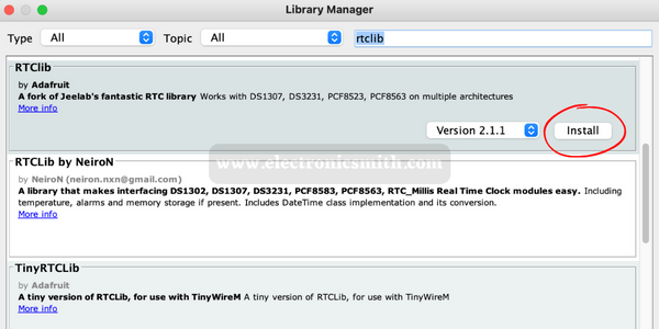
To work with DS3231 Real Time Clock RTC Module You have to include a library go to Sketch > Include Library > Manage Libraries and search for “rtclib” by Adafruit and install it.
// the code is Downloaded from www.electronicsmith.com visit ower website for more tutorials.

#include <Wire.h>
#include <Adafruit_Sensor.h>
#include <Adafruit_BME280.h>

#define SEALEVELPRESSURE_HPA (1013.25)

Adafruit_BME280 bme;

void setup() {
    Serial.begin(9600);

    if (!bme.begin(0x76)) {
        Serial.println("Could not find a valid BME280 sensor, check wiring!");
        while (1);
    }
}

void loop() {
    Serial.print("Temperature = ");
    Serial.print(bme.readTemperature());
    Serial.println("*C");

    Serial.print("Pressure = ");
    Serial.print(bme.readPressure() / 100.0F);
    Serial.println("hPa");

    Serial.print("Approx. Altitude = ");
    Serial.print(bme.readAltitude(SEALEVELPRESSURE_HPA));
    Serial.println("m");

    Serial.print("Humidity = ");
    Serial.print(bme.readHumidity());
    Serial.println("%");

    Serial.println();
    delay(1000);
}

#include <Wire.h>
#include <ds3231.h>

struct ts t;

void setup() {
  Serial.begin(9600);
  Wire.begin();
  DS3231_init(DS3231_CONTROL_INTCN);
  /*----------------------------------------------------------------------------
  In order to synchronise your clock module, insert timetable values below !
  ----------------------------------------------------------------------------*/
  t.hour=12;
  t.min=30;
  t.sec=0;
  t.mday=25;
  t.mon=12;
  t.year=2019;

  DS3231_set(t);
}

void loop() {
  DS3231_get(&t);
  Serial.print("Date : ");
  Serial.print(t.mday);
  Serial.print("/");
  Serial.print(t.mon);
  Serial.print("/");
  Serial.print(t.year);
  Serial.print("\t Hour : ");
  Serial.print(t.hour);
  Serial.print(":");
  Serial.print(t.min);
  Serial.print(".");
  Serial.println(t.sec);

  delay(1000);
}
FAQs
1. What makes DS1307 and DS3231 different from one another?
Ans:- The timekeeping accuracy is the main distinction between the DS3231 and the DS1370. The DS1307 uses an external 32kHz crystal oscillator for timekeeping, whereas the DS3231 uses an internal oscillator.
2. What is the DS3231’s accuracy level?
Ans:- With precision as fine as 2 ppm in temperatures ranging from 0°C to +40°C, the temperature-compensated crystal oscillator (TCXO) in the DS3231 and DS3234 meets the requirement.
3. Which battery does the DS3231 utilize?
Ans:- The DS3231 utilizes a CR2032 rechargeable cell, although one can change the module slightly to use a non-rechargeable cell instead.