
Remember the days when you have to wait in long lines at a store just for checkout? These are the days of the past. The RFID-based walk-through automatic checkout solution is now available thanks to technological advancement.
Nowadays almost all the stores have it. A person can walk through the door directly and will check every item in the cart because all of them have an RFID tag.
In most cases, RFID-based Arduino projects are used, which is a great choice. The simple reason is that it is cheaper than other similar types of products and can work on low power. The interface is also easy, and its popularity increases yearly among hobbyists.
Working of Sensor
The RFID technology can be divided primarily into two parts, and they are two tags. One tag is attached to the object for identifying purposes, and the other will be for the reader who will read the tag. A reader is nothing, but a radio frequency model joined with an antenna. The antenna is responsible for generating electromagnetic waves of high frequency.

The attached tag will work as a passive device as it does not contain any batteries. The microchip that connects with the label is used for dual purposes. One is storage, and the other one is processing. The primary job of the antenna is receiving and transmitting the signal.
When the tag comes close, the reader will create an electromagnetic field. Due to this, the electrons will move at a rapid pace through the antenna. These electromagnetic field waves will eventually provide power to the chip.
The chip will send the stored information as a radio signal to the reader. This process is known as backscatter. The reader will then detect the backscatter, and after interpreting it, will send the data to the computer or the microcontroller attached to it.
RC522 RFID Pin Out

There are a total of 8 pins connecting the RFID module with the outer world. All of the connections are as follows.
VCC: The VCC works as the power supplier of the module. The power range will be between 2.5 volts to 3.3 volts. From your Arduino, you will get a maximum of 3.3 volts output. Never connect your module to a 5 volts pin as this is a high chance that the module will get destroyed.
RST: You can use RST input to reset and power down your module. The module will automatically enter the power-down mode. All the input pins will be disconnected, which in turn, will turn off the oscillator. In the meantime, will put the module on reset.
GND: You need to connect the GND pin with your Arduino module as it works as the ground pin.
IRQ: Whenever there is an RFID tag near the module, the microcontroller will get an alert due to the presence of this interruption tag.
MISO/ SCL/ Tx: After the SPI interface is enabled, the pin will act as master-in-slave-out or perform as a serial clock after enabling the I2C interface. Moreover, it will also work in serial data output once the UART interface is enabled.
MOSI (Master Out Slave In): This one is the SPI input for the RC522 module.
SCK (Serial Clock): Arduino here works as the SPI bus master, and the serial clock will accept the pulses provided by the SPI.
SS/ SDA/ Rx: This pin can be used for several purposes. After enabling the SPI interface, the pin will start acting as signal output. It will work as serial data when the 12C interface is enabled. This pin is used as a marker.
Material Required
The RC522 Reader Kit comes with an RC522 RFID Reader Module, RFID card, RFID Key Fob, and a pair of male headers to solder.
| Name | Quantity |
| RFID Card | 1 |
| RFID key fob | 1 |
| Arduino Uno | 1 |
| Jumper Wires | as per requires |
On the other hand, the RFID Reader Module is packed with MFRC522 IC, a 27.12 MHz Crystal Oscillator. The antenna remains embedded on the PCB, and a maximum of 13.56 MHz electromagnetic field gets produced from the supporting passive components.
Note:- While using it, the user should remember that the MFRC522 IC functions at a supply voltage of 2.5 volts to 3 volts. Ensure that the power supply voltage is not exceeding the 3 volts limit, whereas all the communication pins can bear up to 5 volts.
Circuit Connection (Explain Connections)
Now that you have become aware of the module specifications, it is time to discuss how we can connect the module to Arduino.
First, you need to connect the VCC pin to generate 3.3 volts output from the module, and the GND pin also needs to be attached to the ground on Arduino. Any digital pin can connect the RST pin to the Arduino. We recommend you to join the digital pin to pin #5. In most cases, the IRQ pin remains unconnected as the Arduino library doesn’t support it.
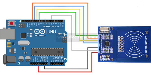
| Pin | Wiring to Arduino Uno |
| SDA | Digital 10 |
| SCK | Digital 13 |
| MOSI | Digital 11 |
| MISO | Digital 12 |
| IRQ | unconnected |
| GND | GND |
| RST | Digital 9 |
| 3.3V | 3.3V |
Code to read tags
Go to sketch>Libraries>manage libraries. Type MFRC522 and include RFID MFRC522v2 by GithubCommunity.

Arduino codes are not that difficult to understand. You can write customized data on an RFID tag. A sample code is mentioned below.
/*
 *
 * All the resources for this project: https://electronicsmith.com/
 *
 *
 */
#include <MFRC522v2.h>
#include <MFRC522DriverSPI.h>
//#include <MFRC522DriverI2C.h>
#include <MFRC522DriverPinSimple.h>
#include <MFRC522Debug.h>

MFRC522DriverPinSimple ss_pin(10); // Configurable, see typical pin layout above.

MFRC522DriverSPI driver{ss_pin}; // Create SPI driver.
//MFRC522DriverI2C driver{}; // Create I2C driver.
MFRC522 mfrc522{driver};  // Create MFRC522 instance.

void setup() {
  Serial.begin(115200);  // Initialize serial communications with the PC for debugging.
  while (!Serial);     // Do nothing if no serial port is opened (added for Arduinos based on ATMEGA32U4).
  mfrc522.PCD_Init();  // Init MFRC522 board.
  MFRC522Debug::PCD_DumpVersionToSerial(mfrc522, Serial);	// Show details of PCD - MFRC522 Card Reader details.
	Serial.println(F("Scan PICC to see UID, SAK, type, and data blocks..."));
}

void loop() {
	// Reset the loop if no new card present on the sensor/reader. This saves the entire process when idle.
	if ( !mfrc522.PICC_IsNewCardPresent()) {
		return;
	}

	// Select one of the cards.
	if ( !mfrc522.PICC_ReadCardSerial()) {
		return;
	}

	// Dump debug info about the card; PICC_HaltA() is automatically called.
  MFRC522Debug::PICC_DumpToSerial(mfrc522, Serial, &(mfrc522.uid));
}
The above code will give you card UID as I mark in the following image. This unique text is the key to your card. we gona use this key in the following code.

RC522 RFID connection with Arduino and LCD
To avoid the complex connection use an Arduino LCD display with the I2C module. All connection is the same as above.

RFID Code with Arduino and LCD
The following code demonstrates access or denies access until the right tag is taped and the output will be displayed on a LCD.
/*
 *
 * All the resources for this project: https://electronicsmith.com/
 *
 *
 */
#include <SPI.h>
#include <MFRC522.h>
#include <LiquidCrystal.h>

#define RST_PIN 9
#define SS_PIN 10

byte readCard[4];
String MasterTag = "BD31152B";  // REPLACE this Tag ID with your Tag ID!!!
String tagID = "";

// Create instances
MFRC522 mfrc522(SS_PIN, RST_PIN);
LiquidCrystal lcd(7, 6, 5, 4, 3, 2); //Parameters: (rs, enable, d4, d5, d6, d7)

void setup()
{
  // Initiating
  SPI.begin(); // SPI bus
  mfrc522.PCD_Init(); // MFRC522
  lcd.begin(16, 2); // LCD screen

  lcd.clear();
  lcd.print(" Access Control ");
  lcd.setCursor(0, 1);
  lcd.print("Scan Your Card>>");
}

void loop()
{

  //Wait until new tag is available
  while (getID())
  {
    lcd.clear();
    lcd.setCursor(0, 0);

    if (tagID == MasterTag)
    {

      lcd.print(" Access Granted!");
      // You can write any code here like opening doors, switching on a relay, lighting up an LED, or anything else you can think of.
    }
    else
    {
      lcd.print(" Access Denied!");
    }

      lcd.setCursor(0, 1);
      lcd.print(" ID : ");
      lcd.print(tagID);

    delay(2000);

    lcd.clear();
    lcd.print(" Access Control ");
    lcd.setCursor(0, 1);
    lcd.print("Scan Your Card>>");
  }
}

//Read new tag if available
boolean getID()
{
  // Getting ready for Reading PICCs
  if ( ! mfrc522.PICC_IsNewCardPresent()) { //If a new PICC placed to RFID reader continue
  return false;
  }
  if ( ! mfrc522.PICC_ReadCardSerial()) { //Since a PICC placed get Serial and continue
  return false;
  }
  tagID = "";
  for ( uint8_t i = 0; i < 4; i++) { // The MIFARE PICCs that we use have 4 byte UID
  //readCard[i] = mfrc522.uid.uidByte[i];
  tagID.concat(String(mfrc522.uid.uidByte[i], HEX)); // Adds the 4 bytes in a single String variable
  }
  tagID.toUpperCase();
  mfrc522.PICC_HaltA(); // Stop reading
  return true;
}