Non-contact infrared temperature scanners have become more common since the introduction of COVID-19, appearing at restaurants and airports worldwide. You might be interested in creating one or just intrigued by these temperature scanners. The Melexis MLX90614 Module may therefore be the most cost-effective choice available in that situation.
Working of sensor
Infrared thermometers like the MLX90614 make use of the fact that everything, including people, above the temperature of absolute zero (0°K or -273°C) produces light in the infrared band that is directly proportional to its temperature.
The MLX90614 has two components: an ASSP, an infrared thermopile detector, and an ab Signal-Conditioning Application Processor. This MLX90614 internal block diagram illustrates both the thermopile and the ASSP.

Thermopiles are specialized infrared detectors that capture the IR radiation that an item or human releases. The thermopile measures the amount of infrared energy radiated by objects in its field of view (FOV) and produces an electrical output proportionate to that.
An IR thermometer’s field-of-view (FOV) is among the most crucial measurements to be aware of.
The sensor’s sensitivity to thermal radiation at a given angle determines it. As a result, the sensor will pick up on every object in its field of vision and send back its average temperature.

The ASSP’s 17-bit ADC detects the voltage generated by the thermopile and processes it before sending it to the microcontroller.
The best part is that this entire process can be completed in a split second.
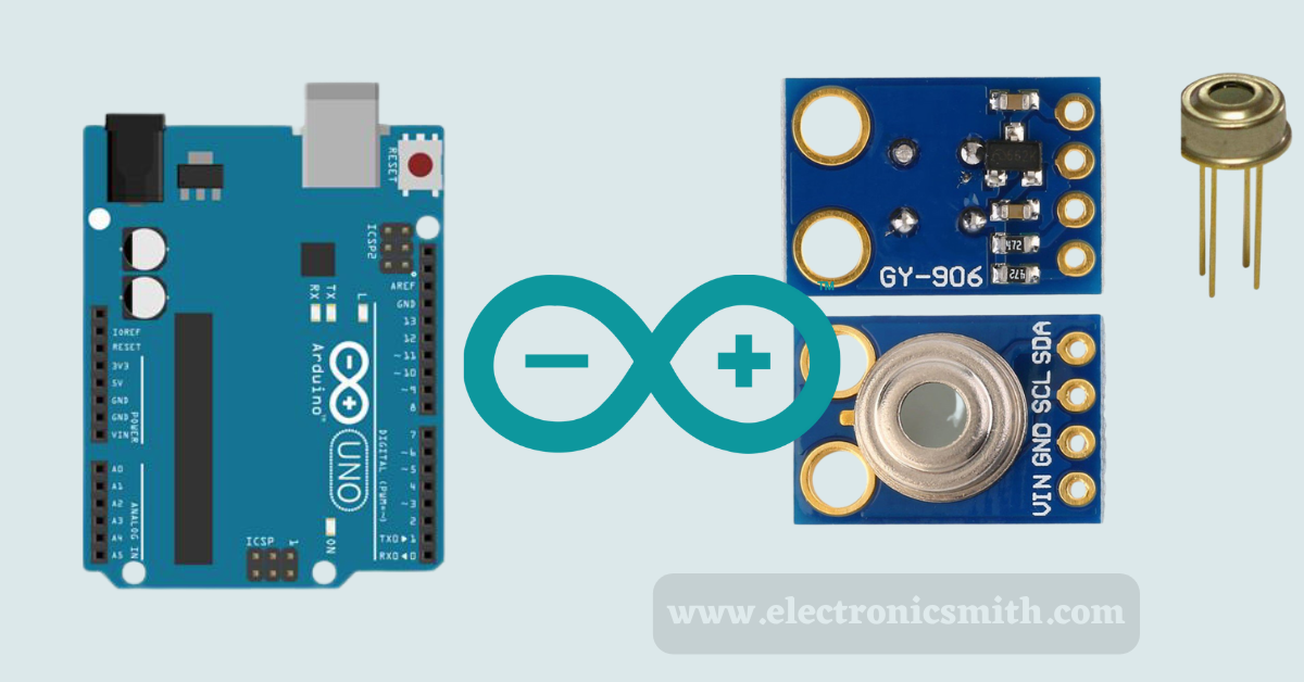
Material required
The following materials are required for this tutorial.
| S. No. | Items | Quantity |
| 1. | Arduino UNO | 1 |
| 2. | Wires | as per requirements |
| 3. | MLX90614 IR sensor | 1 |
| 6. | Battery | 1 |
MLX90614 Module Hardware Overview
MLX90614 Output Interfaces
Although you need one to access the other, the MLX90614 supports two interfaces. The MLX90614 can be reached primarily using a 2-wire SMBus interface. After setting up the SMBus interface, you may later configure the MLX90614 to generate a PWM (pulse-width-modulated) signal representing the observed temperature.
Input/Output SMBus
The MLX90614’s main interface is a 2-wire SMBus interface, essentially identical to I2C, a slightly non-standard variant of I2C dubbed also called “repeated-start” and makes use of the same two signals, SDA and SCL, for data and clock signals, respectively. The clock signal is controlled by a controller device, whereas the data signal is controlled by bi-directional control.
The default I2C address for every MLX90614 is 0x5A. To get a wider temperature map, you can connect up to 127 devices to the same bus by programming it to have one of 127 I2C addresses.
Interfacing PWM
The PWM interface also allows data from the MLX90614 to be accessed. It should be noted that the MLX90614 must first be configured through the SMBus before using the PWM interface.
The MLX90614 provides a continuous 10-bit PWM signal on the SDA pin after configuration that indicates the temperature of the object being monitored. The output resolution of the PWM signal, which has a default range of -20°C to 120°C, can also be changed using SMBus.
Thermal Switch/Thermal Relay
The PWM output can be converted into a “Thermal Relay/Thermal Switch” signal by setting the lowest and maximum temperature values within this range.
As a result, the PWM pin, which can be used as an interrupt source or to directly operate a relay, is activated when the temperature exceeds the defined threshold. Notably, the output drive capability is limited to 25mA.
MLX90614 Module Pinout
The MLX90614 module reveals the connections listed below.
VCC: The power pin is VCC. It can be connected to your Arduino’s 3.3V or 5V output.
GND: The pin is for the ground.
SCL: Connect your Arduino’s I2C clock line to the SCL pin, which is the I2C clock pin.
SDA: Connect your Arduino to the I2C data line using the SDA I2C data pin.
Circuit connection
The VCC pin should be connected to the power supply; 5V is acceptable. Use the voltage on which your microcontroller’s logic is based. That is 5V for most Arduinos. Use 3.3V for devices using 3.3V logic. Connect the GND to the common ground now.

On your Arduino, attach the SDA pin to the I2C data pin and the SCL pin to the I2C clock pin. Remember that the I2C pins on each Arduino Board vary, and they must be connected correctly. The SDA (data line) and SCL (clock line) are located on the pin headers close to the AREF pin on Arduino boards with the R3 configuration. They also go by A5 (SCL) and A4 (SDA).
Installation of library
Several libraries are accessible for the MLX90614 sensor. Although the Adafruit library is user-friendly, it only supports simple temperature measurement and not the advanced sensor functionalities in our case. The Arduino IDE Library Manager is where you may download the library from.
Navigate to Sketch, then go to Include Library. After that, go to Manage Libraries to install the library. Type in the search bar adafruit mlx90614, and Install Adafruit MLX90614 Library by Adafruit.

Code
An easy-to-use Arduino program is provided below, enabling simple testing of MLX90614’s functionality. Upload it to your Arduino right now. The temperature of the surrounding area and the object should be printed on the serial interface.
#include <Adafruit_MLX90614.h>

Adafruit_MLX90614 mlx = Adafruit_MLX90614();

Void setup() {
	Serial.begin(9600);
	While (!Serial);

	If (!mlx.begin()) {
		Serial.println(“Error connecting to MLX sensor. Check wiring.”);
		While (1);
	};
}
Void loop() {
	Serial.print(“Ambient = “); Serial.print(mlx.readAmbientTempC());
	Serial.print(“*C\tObject = “); Serial.print(mlx.readObjectTempC()); Serial.println(“*C”);
	Serial.print(“Ambient = “); Serial.print(mlx.readAmbientTempF());
	Serial.print(“*F\tObject = “); Serial.print(mlx.readObjectTempF()); Serial.println(“*F”);

	Serial.println();
	Delay(500);
}
Open your serial monitor after the sketch has been uploaded, and set the baud rate to 9600 bps. Both the surrounding temperature and the item temperature should start to stream by.
To be sure you don’t have a fever, try pointing the sensor at nearby objects or your forehead.
Code overview
Adafruit MLX90614 library is first incorporated into the sketch. A specified Adafruit MLX90614 object called mix can be found in the same global region.
We use the begin() function and establish the serial connection to the PC during setup.
The I2C interface is initialized using the begin() method. The 7-bit address of your sensor, an optional parameter for this method, must be provided; otherwise, it will presume that the address is set to the default (0x5A).
We already publish articles on the following temperature sensors must read:
- Interface BME280 Temperature, Humidity & Pressure Sensor with Arduino.
- DS18B20 Temperature Sensor and Arduino Interfacing: what you need to know.
- In-depth about the LM35 Temperature Sensors and Arduino interface.
- TMP36 temperature sensor working and Arduino connection
FAQs
Is the MLX90614 Module module used for measuring body temp?
Ans:- Mainly, this sensor is used to measure the temperature of the machine, but it can be used as a thermometer for the human body.
What is the output of the MLX90614 IR module?
Ans:- It may offer the thermometer excellent precision and accuracy. The MLX90614’s most pleasing feature is that it uses the factory’s digital SMBus for calibration. This indicates that it is anticipated to continually communicate a measured temperature between -20 and 120°C and deliver a progressive output of 0.02°C.