If you’ve ever wanted to add more outputs to your Arduino without sacrificing valuable pins, a shift register is a way to go. The shift register increases the number of pins to be used from the Arduino. The 74HC595 is a popular shift register IC that is often used in Arduino projects. It’s easy to interface with and can be used to control a variety of devices.
The 74HC595 is a popular shift register used with Arduino projects because it enables using as many outputs as required with only a fixed number of input pins.
It might be required anytime, so it’s essential to have a strong understanding of the devices you work with. In this article, we’ll show you how a 74HC595 shift register works and how to interface it with an Arduino. By the end, you’ll be able to add an extra 8 outputs to your Arduino project.
Working of 74HC595 Shift Register
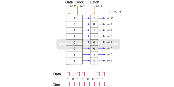
74HC595 Shift Register has an 8-bit storage register and an 8-bit shift register. The device features a storage register and a shift register. Both the storage register and the shift register have parallel 3-state outputs.
When the shift register is clocked, the data in the shift register moves one place to the right, and the data in the storage register moves one place to the left.
When the storage register is clocked, the data in the shift register is transferred to the second register, known as the storage register. And with each bit connected to outputs, with the change in register, the output changes.

Hardware overview
The 74HC595 is an 8-bit shift register with a storage register and 3-state outputs. The device features a serial input (DS) and output (Q7S) for cascading devices. The 74HC595 has an active LOW Enable input (E) and active LOW Reset input (R). The outputs of the shift register are 3-state and can be connected to the inputs of other devices.
Features of 74HC595
- 8-bit serial input
- 8-bit serial or parallel output
- Storage register with 3-state outputs
- Shift register with direct clear
- 100 MHz (typical) shift out frequency
- ESD protection:
- HBM JESD22-A114F exceeds 2000 V
- MM JESD22-A115-A exceeds 200 V
- Multiple package options
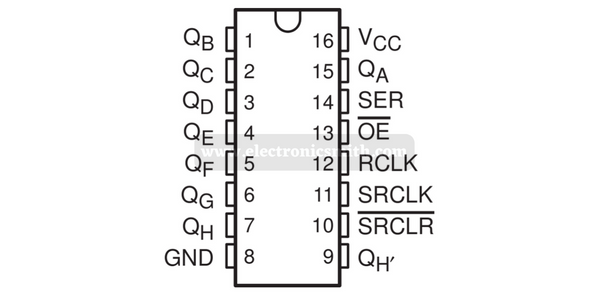
PinOut
74HC595 shift registers are one of the most popular and commonly used ICs, and they come in different models. So, no matter which one is with you. All that is required is to read the datasheet. for detail check data sheet of the IC.

Consisting of the seven pins, here is all that to know about it:
VCC works as a power supply to the first register of 74HC595 when connected with Arduino.
GND, as the name suggests, is connected to the ground.
SRCLK (Shift Register Clock), The shift register clock works for the shift register. The clock is high to shift the bits into the shift register.
RCLK (Register Clock / Latch), when the clock is high, the bits of the shift are copied to the storage register and show output, so register clocks are available at the final steps when output is given.
SRCLR (Shift Register Clear), is only used for resetting the shift register. The only thing to remember is when it is used, it must be low and the rest time high.
OE (Output Enable) works simultaneously; when high voltage is passed, it’s off. And when low voltage is passed, it usually works.
QH, is used to daisy chain the 595 sensors. If they are connected, they work as dual or several channels providing as many outputs as required.
Material required
| Components | Qty. |
| Arduino UNO | 1 |
| USB Cable Type A to B | 1 |
| Jumper Wires | – |
| 74HC595 Shift Register | 1 |
Circuit connection
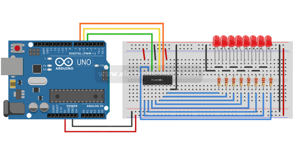
To connect this with Arduino, all the information must be known. Here is all explained well about it.
- Place the 1st register on the breadboard with both IC separated.
- The upper pins would be visible on the left, and the bottom ones on the right.
Now, some of the pins need to be connected to the Arduino. Here are the ones which are required to be connected.
- Shift register clock pin to pin 6 of Arduino.
- Register clock to pin 5 of Arduino.
- Shift register clear to pin 4 of Arduino.
After this, all the output pins are required to be connected to LEDs. The connection order must be right, and the QA is wired first while QH is wired to the last LED.

Code
For the output here is the Arduino code to be used:
//...............................................
//for more tutorial check
//electronicsmith.com
//................................................

int latchPin = 5;	// Latch pin of 74HC595 is connected to Digital pin 5
int clockPin = 6;	// Clock pin of 74HC595 is connected to Digital pin 6
int dataPin = 4;	// Data pin of 74HC595 is connected to Digital pin 4

byte leds = 0;		// Variable to hold the pattern of which LEDs are currently turned on or off

/*
 * setup() - this function runs once when you turn your Arduino on
 * We initialize the serial connection with the computer
 */
void setup()
{
  // Set all the pins of 74HC595 as OUTPUT
  pinMode(latchPin, OUTPUT);
  pinMode(dataPin, OUTPUT);
  pinMode(clockPin, OUTPUT);
}
/*
 * loop() - this function runs over and over again
 */
void loop()
{
  leds = 0;	// Initially turns all the LEDs off, by giving the variable 'leds' the value 0
  updateShiftRegister();
  delay(500);
  for (int i = 0; i < 8; i++)	// Turn all the LEDs ON one by one.
  {
    bitSet(leds, i);		// Set the bit that controls that LED in the variable 'leds'
    updateShiftRegister();
    delay(500);
  }
}
/*
 * updateShiftRegister() - This function sets the latchPin to low, then calls the Arduino function 'shiftOut' to shift out contents of variable 'leds' in the shift register before putting the 'latchPin' high again.
 */
void updateShiftRegister()
{
   digitalWrite(latchPin, LOW);
   shiftOut(dataPin, clockPin, LSBFIRST, leds);
   digitalWrite(latchPin, HIGH);
}
Connect multiple 74HC595 Shift Register with Arduino
Interestingly, several shift registers can be connected in series. This increases the number of possible outputs without the Arduino pins used becoming more.
Connection with Arduino
Connection is easy for reference to follow the following image.

Code
Copy the code and upload it to Arduino.
//...............................................
//for more tutorial check
//electronicsmith.com
//................................................

//Pin connected to ST_CP of 74HC595
int latchPin = 5;
//Pin connected to SH_CP of 74HC595
int clockPin = 6;
////Pin connected to DS of 74HC595
int dataPin = 4;
void setup() {
  //set pins to output so you can control the shift register
  pinMode(latchPin, OUTPUT);
  pinMode(clockPin, OUTPUT);
  pinMode(dataPin, OUTPUT);
}
void loop() {
  // count from 0 to 255 and display the number
  // on the LEDs
  for (int numberToDisplay = 0; numberToDisplay < 256; numberToDisplay++) {
    // take the latchPin low so
    // the LEDs don't change while you're sending in bits:
    digitalWrite(latchPin, LOW);
    // shift out the bits:
    shiftOut(dataPin, clockPin, MSBFIRST, numberToDisplay);
    shiftOut(dataPin, clockPin, MSBFIRST, 255-numberToDisplay);
    //take the latch pin high so the LEDs will light up:
    digitalWrite(latchPin, HIGH);
    // pause before next value:
    delay(500);
  }
}
FAQs
What is a Shift Register?
A Serial-to-Parallel Converter IC is a Shift Register. It effectively reduces the number of interface pins between a Microcontroller and its output devices by taking a serial input through a single pin.
What are the control signals for 74HC595?
The three control signals available in serial order from the microcontroller, Arduino, are:
- Serial Data In.
- Serial Clock.
- Latch Clock.
How does the 74HC595 shift register work?
A shift register that uses the Serial IN Parallel OUT protocol is the 74HC595. It transfers data received in serial form from the microcontroller to parallel pins for output. Using a single device, we may expand our output pins by eight. Additionally, we can connect many shift registers simultaneously.
What can I do with a 74HC595?
A shift register that uses the Serial IN Parallel OUT protocol is the 74HC595. It transfers data received in serial form from the microcontroller to parallel pins for output. Using a single device, we may expand our output pins by eight.
When to use Shift Register?
As for the fact that each microcontroller only has a certain amount of I/O pins, on microcontrollers, shift registers are widely used to conserve pins (GPIO). And it’s used when the pins are increased with the same input.
