
The Arduino Nano is a small, inexpensive microcontroller board based on the ATmega328P. It has a number of features that make it ideal for projects that require simple I/O, such as button presses or reading sensors. It also has numerous built-in functions for flashing firmware and uploading code to it.
Arduino Nano Overview
It is a microcontroller board, designed to make it easy to get started with electronics and programming. It’s compatible with Arduino shields, so you can use it to easily teach yourself how to program, or build your own custom projects. The nano is powered by an ATmega328 microcontroller, which has an operating voltage of 5V and can be programmed using the Arduino IDE (Integrated Development Environment).

The Arduino nano has a total of 20 input/output pins (of which 14 can be used as Digital/PWM I/O), 6 analog I/O, 4 UARTs (serial ports), a Type-B USB connection, an ICSP header for connecting to a USB-to-TTL Serial cable or adapter, 16 MHz crystal oscillator and a reset button.
It contains everything needed to support the microcontroller; simply connect it to a computer with a USB cable or power it with an AC-to-DC adapter or battery to get started. It also has a 5V Regulator and USB-to-Serial Converter IC are the main components.

The main difference between the Arduino Uno and the Arduino Nano is that the Nano has a smaller form factor, which makes it easier to carry around. The Nano has fewer pins than the Uno, but its functionality is identical. For more comparison refer to Arduino Uno pinout and their function.
Arduino nano board Specifications
The technical specifications of the Arduino Nano are as follows:
| MCU | ATmega328P |
| Architecture | AVR |
| Operating Voltage | 5V |
| Input Voltage | 5V – 12V |
| Clock Speed | 16 MHz |
| Flash Memory | 32 KB |
| SRAM | 2 KB |
| EEPROM | 1 KB |
| Digital IO Pins | 14 |
| Analog IO Pins | 6 |
Communication Interfaces are available on Arduino Nano?
Arduino Nano supports three different types of communication interfaces:
- Serial
- I2C or I2C (Inter-Integrated Circuit)
- SPI (serial peripheral interface)
Arduino nano Pinout and function
Let us now see the pinout description of Arduino nano, but before that let us assume some names for the pins to easily understand their working.
| Arduino Nano Pin | Pin Name | Type | Function |
| 1 | D1/TX | I/O | Digital I/O PinSerial TX Pin |
| 2 | D0/RX | I/O | Digital I/O PinSerial RX Pin |
| 3 | RESET | Input | Reset ( Active Low) |
| 4 | GND | Power | Supply Ground |
| 5 | D2 | I/O | Digital I/O Pin |
| 6 | D3 | I/O | Digital I/O Pin |
| 7 | D4 | I/O | Digital I/O Pin |
| 8 | D5 | I/O | Digital I/O Pin |
| 9 | D6 | I/O | Digital I/O Pin |
| 10 | D7 | I/O | Digital I/O Pin |
| 11 | D8 | I/O | Digital I/O Pin |
| 12 | D9 | I/O | Digital I/O Pin |
| 13 | D10 | I/O | Digital I/O Pin |
| 14 | D11 | I/O | Digital I/O Pin |
| 15 | D12 | I/O | Digital I/O Pin |
| 16 | D13 | I/O | Digital I/O Pin |
| 17 | 3V3 | Output | +3.3V Output (from FTDI) |
| 18 | AREF | Input | ADC reference |
| 19 | A0 | Input | Analog Input Channel 0 |
| 20 | A1 | Input | Analog Input Channel 1 |
| 21 | A2 | Input | Analog Input Channel 2 |
| 22 | A3 | Input | Analog Input Channel 3 |
| 23 | A4 | Input | Analog Input Channel 4 |
| 24 | A5 | Input | Analog Input Channel 5 |
| 25 | A6 | Input | Analog Input Channel 6 |
| 26 | A7 | Input | Analog Input Channel 7 |
| 27 | +5V | Output or Input | +5V Output (From On-board Regulator) or+5V (Input from External Power Supply |
| 28 | RESET | Input | Reset ( Active Low) |
| 29 | GND | Power | Supply Ground |
| 30 | VIN | Power | Supply voltage |
ICSP PINS
| Arduino Nano ICSP Pin Name | Type | Function |
| MISO | Input or Output | Master In Slave Out |
| Vcc | Output | Supply Voltage |
| SCK | Output | Clock from Master to Slave |
| MOSI | Output or Input | Master Out Slave In |
| RST | Input | Reset (Active Low) |
| GND | Power | Supply Ground |
Arduino Nano Digital Pins
The digital pins are designed to be configured as inputs or outputs according to the needs of the user.
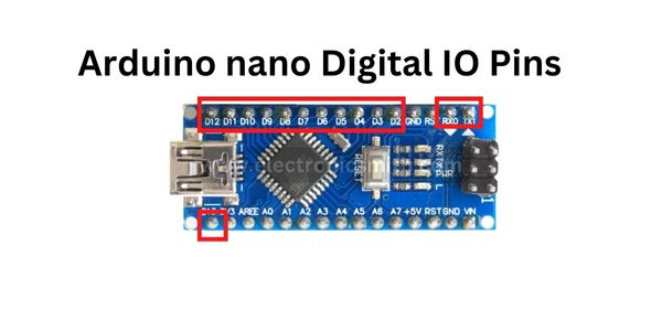
Digital pins are either on or off. When digital pins are on they are in a high voltage state of 5 volts and when they are off they are in a low voltage state of 0 volts.
As we know Arduino nano digital pins consist of a total of 14 digital input/output pins. The number of pins is as follows:-
The numbers are printed on the board in this format Tx1, RX0, D2, D3, D4, D5, D6, D7, D8, D9, D10, D11, D12, and D13.
All of the above-mentioned pins work on 5V voltage. Each pin can receive or provide 40mA.
PWM Pins
PWM stands for “Pulse Width Modulation”. These pins are used to get analog results with digital means.

It consists of the following pins:-
~D3, ~D5, ~D6, ~D9, ~D10 and ~D11.
(~) this symbol means the pin can use in PWM mode.
The above digital pins provide a Pulse Width Modulation signal of 8-bit resolution.
Interrupts
We use these pins when we need to provide an interrupt to another processor or controller.

For providing interrupts we can use these pins to enable interrupts INT0 and INT1 respectively by using the attachInterrupt () function.
It consists of the following pins:- D2, and D3.
LED pin
LED or “Light Emitting Diode” are used to blink. An LED is attached to this pin mostly for testing purposes.

It consists of pin D13
Arduino Nano Analog Pins
It consists of the following pins:- A0, A1, A2, A3, A4, A5, A6, and A7.

The pins are measured from the ground to 5V.
Serial Communication Pins
Serial communication pins are used for transferring data in serial mode from one device to another device.

It consists of the following pins:-
1 and 2 where 1 = RX and 2 = TX
Both of the above pins RX-receive and TX-transmit are used for serial communication.
SPI Pins
These pins are used when we don’t need data to be transmitted asynchronously.
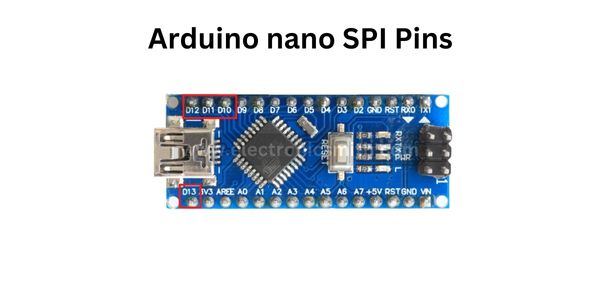
It consists of the following pins:- 10 (SS), 11 (MOSI), 12 (MISO), 13 (SCK)
I2C Pins
SDA (Serial data line) and SCL (Serial clock line) are on the A4 and A5 pin headers respectively.

For long-distance communication, we use the I2C protocol.
I2C supports multi-master and multi-slave with only two wires one for data and one for the clock.
AREF Pin
This pin is used as a reference voltage for analog input for the ADC conversion.
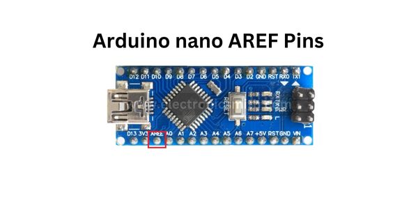
Pin no.18 of Arduino is AREF pin
Reset Pin
It is an active low pin, used to reset the controller. Active low means if the value of the pin is low then it will be active and vice versa.

ICSP
Circuit Serial Programming or ICSP is used to program an Arduino board. ICSP can be used in place of a missing bootloader.
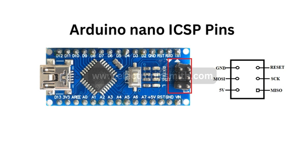
Each ICSP pin is cross-connected with another Arduino pin with the same name and the same function.
4 thoughts on “Arduino nano pinout & Their functions”