
A TM 1637 4-digit 7-segment display is a type of digital clock with four digits and seven segments. It displays hours, minutes, and seconds in two modes: as hours/minutes or as hours/seconds.
The TM 1637 was developed by Texas Instruments in 1978, with production beginning in 1979. Over 500 million units have been produced worldwide since then; they are still widely used today.
Despite its age, 1637 remains popular due to its accuracy and durability. It is also easy for beginners to use, making it a popular choice for hobbyists.
About the TM 1637 4 digit
Display
The TM 1637 4-digit display is a 7-segment LED display with an LCD driver. It has 4 digits and each digit can display up to 8 values, making it possible to display in this format.
Basically, 4-digit 7-segment displays usually require 12 connection pins, but the TM1637 reduces the total wire to 4 Two pins are required for the power connections and the other two pins are used to control the segments.
TM1637 is responsible for all the work of refreshing the display and in this way it removes the overhead from the microcontroller.
TM1637 Hardware Overview
4-digit 7-segment displays are simply an arrangement of four seven-segment display modules that use the multiplexing technique so that they can be used on microcontrollers with a limited amount of I/O pins.

The TM1637 module includes four 0.36″ segment 7-segment displays. The module has a ‘colon’ at the center used to create clock or time-based projects and also used to create temperature sensors.
At the back of the display, there is an inexpensive serial LED driver from Titan MicroElectronics called TM1637.
Working of 4 digit 7 segment display
There are 7 segments in the form of digit 8 used to form any 4 valued digits. The 4 pins out of 12 pins control the 4 digits on display.

Below are some examples of how digits can be displayed on the TM1637 4 digit 7 segment display
Features of TM 1637 4 digits 7 segment display
- TM 1637 is a chip for driving 7-segment displays with brightness control.
- The chip is a 7-segment display driver. It works in I2C protocol and has an address pin for using multiple of these modules on a single bus.
- The TM 1637 can be used as the most powerful microcontroller board for driving high-brightness LED displays, including the 7-Segment LED Displays.
- It has built-in registers for data storage, does not require any external memory modules
- The Arduino module operates on 3.3V to 5V with 80mA of current. We can interface TM1637 with Arduino or any other microcontroller using the two data pins SDA and SCL. There is multiple TM1637 Library available for Arduino that helps in removing the complexities and makes it easier to communicate with the display.
- It is comparatively cheaper than other display modules.
- Potable and durable so it can withstand even in adverse environmental conditions for a long period of time.
- Many pre-written programs for controlling the TM1637 display module are available for free which makes its use very simple for non-programmers also.
Pinout of TM1637 4 digit 7 segment display

The TM1637 display module has only four pins, they are:-
CLK(Clock): It is used for data input and output at the rising edge.
DIO(Data Input/ Output): It is used for serial data input or output
VCC: It is connected to a 5V power supply. The module can work on up to +5V regulated power and higher voltages may lead to permanent damage.
GND: It is connected to the ground
Material required
| Material | Description | Quantity |
| Arduino Board | Arduino Nano Board Atmega328. | 1 |
| TM1637 | 4Digit 7-Segment Display | 1 |
| DS3231 | Real-Time Clock Module. | 1 |
| DHT22/11 | Humidity & Temperature Sensor. | 1 |
| Jumper wires | Male-to-Male Jumper Wires. | 20 |
| Breadboard | Solderless Breadboard. | 1 |
TM1637 4 digit 7 segment display with Arduino Tutorial
Connection diagram
The display is connected to the Arduino via the 5V and GND pins. It has an I2C interface, so you can also use any microcontroller compatible with that protocol (like a Raspberry Pi) to control it.
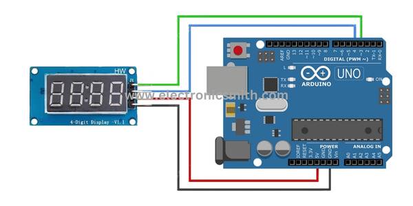
Connect the ground to the Arduino GND.
Connect the power supply to the Arduino 5V.
Connect the data pin (D6) of your microcontroller to one side of an external pull-up resistor and then connect it to another output on your microcontrollers, such as 3V or 5V.
How to install the library
There are several libraries available but TM1637 by “Avishay Orpaz” is the most popular one. This library has several built-in functions that make controlling the display simple.
To download the TM1637 Library we can use the GitHub Link.
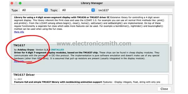
We also can visit the Library manager and install the library directly by Searching ‘tm1637‘ & checking for the library by Avishay Orpaz. Click on that and then select Install.
Code for interfacing Arduino with TM1637 4 digit 7 segment display
Copy and upload the code to your Arduino board.
#include <Arduino.h>
#include <TM1637Display.h>

// Module connection pins (Digital Pins)
#define CLK 3
#define DIO 4

// The amount of time (in milliseconds) between tests
#define TEST_DELAY   2000

const uint8_t SEG_DONE[] = {
    SEG_B | SEG_C | SEG_D | SEG_E | SEG_G,           // d
    SEG_A | SEG_B | SEG_C | SEG_D | SEG_E | SEG_F,   // O
    SEG_C | SEG_E | SEG_G,                           // n
    SEG_A | SEG_D | SEG_E | SEG_F | SEG_G            // E
    };

TM1637Display display(CLK, DIO);

void setup()
{
}

void loop()
{
  int k;
  uint8_t data[] = { 0xff, 0xff, 0xff, 0xff };
  uint8_t blank[] = { 0x00, 0x00, 0x00, 0x00 };
  display.setBrightness(0x0f);

  // All segments on
  display.setSegments(data);
  delay(TEST_DELAY);
// Selectively set different digits
  data[0] = display.encodeDigit(0);
  data[1] = display.encodeDigit(1);
  data[2] = display.encodeDigit(2);
  data[3] = display.encodeDigit(3);
  display.setSegments(data);
  delay(TEST_DELAY);

  /*
  for(k = 3; k >= 0; k--) {
    display.setSegments(data, 1, k);
    delay(TEST_DELAY);
    }
  */

  display.clear();
  display.setSegments(data+2, 2, 2);
  delay(TEST_DELAY);

  display.clear();
  display.setSegments(data+2, 2, 1);
  delay(TEST_DELAY);

  display.clear();
  display.setSegments(data+1, 3, 1);
  delay(TEST_DELAY);


  // Show decimal numbers with/without leading zeros
  display.showNumberDec(0, false); // Expect: ___0
  delay(TEST_DELAY);
  display.showNumberDec(0, true);  // Expect: 0000
  delay(TEST_DELAY);
    display.showNumberDec(1, false); // Expect: ___1
    delay(TEST_DELAY);
  display.showNumberDec(1, true);  // Expect: 0001
  delay(TEST_DELAY);
  display.showNumberDec(301, false); // Expect: _301
  delay(TEST_DELAY);
  display.showNumberDec(301, true); // Expect: 0301
  delay(TEST_DELAY);
  display.clear();
  display.showNumberDec(14, false, 2, 1); // Expect: _14_
  delay(TEST_DELAY);
display.clear();
  display.showNumberDec(4, true, 2, 2);  // Expect: 04__
  delay(TEST_DELAY);
  display.showNumberDec(-1, false);  // Expect: __-1
  delay(TEST_DELAY);
  display.showNumberDec(-12);        // Expect: _-12
  delay(TEST_DELAY);
  display.showNumberDec(-999);       // Expect: -999
  delay(TEST_DELAY);
  display.clear();
  display.showNumberDec(-5, false, 3, 0); // Expect: _-5_
  delay(TEST_DELAY);
  display.showNumberHexEx(0xf1af);        // Expect: f1Af
  delay(TEST_DELAY);
  display.showNumberHexEx(0x2c);          // Expect: __2C
  delay(TEST_DELAY);
  display.showNumberHexEx(0xd1, 0, true); // Expect: 00d1
  delay(TEST_DELAY);
  display.clear();
  display.showNumberHexEx(0xd1, 0, true, 2); // Expect: d1__
  delay(TEST_DELAY);

    // Run through all the dots
    for(k=0; k <= 4; k++) {
        display.showNumberDecEx(0, (0x80 >> k), true);
        delay(TEST_DELAY);
    }

  // Brightness Test
  for(k = 0; k < 4; k++)
    data[k] = 0xff;
  for(k = 0; k < 7; k++) {
    display.setBrightness(k);
    display.setSegments(data);
    delay(TEST_DELAY);
  }

  // On/Off test
  for(k = 0; k < 4; k++) {
    display.setBrightness(7, false);  // Turn off
 display.setSegments(data);
    delay(TEST_DELAY);
    display.setBrightness(7, true); // Turn on
    display.setSegments(data);
    delay(TEST_DELAY);
  }


  // Done!
  display.setSegments(SEG_DONE);

  while(1);
}
The TM1637 Display will immediately turn ON and starts displaying the random numbers and characters as per the code.
Code explanation
The code starts with including the library.
#include <Arduino.h>
#include <TM1637Display.h>
Then we need to specify the connection pins for CLK & DIO.
#define CLK 3
#define DIO 4
We created arrays to spell words. Each segment is separated by a | and the digits of the display are separated by a comma. This array will display “done” on LED Display.
const uint8_t SEG_DONE[] = {
    SEG_B | SEG_C | SEG_D | SEG_E | SEG_G,           // d
    SEG_A | SEG_B | SEG_C | SEG_D | SEG_E | SEG_F,   // O
    SEG_C | SEG_E | SEG_G,                           // n
    SEG_A | SEG_D | SEG_E | SEG_F | SEG_G            // E
    };
It is the amount of time in milliseconds between the tests. It means that the next thing will be displayed after an interval of 200 milliseconds.
#define TEST_DELAY 2000
Then we need to create a new instance of the TM1637Display class with the function TM1637Display().
This function requires two parameters, first the CLK pin and the second the DIO pin.
TM1637Display display(CLK, DIO);
The first option is to set individual segments is to use hexadecimal numbers.
Hexadecimal 0xFF translates to 11111111 in binary, and it turns all segments ON while 0x00 will turn OFF all segments.
uint8_t data[] = { 0xff, 0xff, 0xff, 0xff };
  uint8_t blank[] = { 0x00, 0x00, 0x00, 0x00};
This function is used to manage the brightness of the display using setBrightness(brightness, on).
We can specify a brightness level from 0 (lowest brightness) to 7 (highest brightness). We can pass it as true (display ON) or false (display OFF).
display.setBrightness(7, false);  // Turn off
display.setBrightness(7, true); // Turn on
This function can be used to set individual segments of a display.
The first argument is the array that contains the segment information.
The second argument specifies the number of digits to be updated between 0 to 4.
The third argument determines the position from which you want to print (0-leftmost, 3-rightmost).
display.setSegments(data);
display.setSegments(data+2, 2, 2);
Let us see how can we use TM1637 to construct a temperature monitor using DHT11
In this tutorial, we will display the temperature on the TM1637 module.
Connection Diagram
For connection, refer DHT11 Module Temperature and Humidity sensor Arduino interface we already publish.

Code
// Include the libraries
#include <TM1637Display.h>
#include <Adafruit_Sensor.h>
#include <DHT.h>

// Define the connections pins
#define CLK 3
#define DIO 4
#define DHTPIN 2

// Create variable
int temperature_celsius;
int temperature_fahrenheit;

// Create °C symbol
const uint8_t celsius[] = {
  SEG_A | SEG_B | SEG_F | SEG_G,  // Circle
  SEG_A | SEG_D | SEG_E | SEG_F   // C
};

// Create °F symbol
const uint8_t fahrenheit[] = {
  SEG_A | SEG_B | SEG_F | SEG_G,  // Circle
  SEG_A | SEG_E | SEG_F | SEG_G   // F
};

// Uncomment whatever type you're using!
//#define DHTTYPE DHT11   // DHT 11
#define DHTTYPE DHT22   // DHT 22  (AM2302)

// Create display object of type TM1637Display
TM1637Display display = TM1637Display(CLK, DIO);

// Create dht object of type DHT:
DHT dht = DHT(DHTPIN, DHTTYPE);

void setup() {
  // Set the display brightness (0-7)
  display.setBrightness(5);

  // Clear the display
  display.clear();

  // Setup sensor
  dht.begin();
}

void loop() {
  // Read the temperature as Celsius and Fahrenheit
  temperature_celsius = dht.readTemperature();
  temperature_fahrenheit = dht.readTemperature(true);

  // Display the temperature in celsius format
  display.showNumberDec(temperature_celsius, false, 2, 0);
  display.setSegments(celsius, 2, 2);
  delay(1000);

  // Display the temperature in fahrenheit format
  display.showNumberDec(temperature_fahrenheit, false, 2, 0);
  display.setSegments(fahrenheit, 2, 2);
  delay(1000);
}
Connect multiple TM1637 with Arduino
In this tutorial, we will connect six TM1637 with a single Arduino and display time.
Connect different power source to power tm1637 module because each module take upto 30 to 80mA and combine 6 will take aprox 480mA. Arduino is unable to deliver that much current.

Code
#include <TimerOne.h>
#include "TM1637.h"
TM1637 tm1637(1,2);
TM1637 tm1637a(3,4);
TM1637 tm1637b(5,6);
TM1637 tm1637c(7,8);
TM1637 tm1637d(9,10);
TM1637 tm1637e(11,12);

void setup()
{
tm1637.init();
tm1637.set(BRIGHT_TYPICAL);
tm1637a.init();
tm1637a.set(BRIGHT_TYPICAL);
tm1637b.init();
tm1637b.set(BRIGHT_TYPICAL);
tm1637c.init();
tm1637c.set(BRIGHT_TYPICAL);
tm1637d.init();
tm1637d.set(BRIGHT_TYPICAL);
tm1637e.init();
tm1637e.set(BRIGHT_TYPICAL);
}

void loop()
{
int a=7,b=53;
int a1,a2,a3,a4;
a1=a/10;
a2=a%10;
a3=b/10;
a4=b%10;

tm1637.display(0,a1);
tm1637.display(1,a2);
tm1637.display(2,a3);
tm1637.display(3,a4);
tm1637a.display(0,a1);
tm1637a.display(1,a2);
tm1637a.display(2,a3);
tm1637a.display(3,a4);
tm1637b.display(0,a1);
tm1637b.display(1,a2);
tm1637b.display(2,a3);
tm1637b.display(3,a4);
tm1637c.display(0,a1);
tm1637c.display(1,a2);
tm1637c.display(2,a3);
tm1637c.display(3,a4);
tm1637d.display(0,a1);
tm1637d.display(1,a2);
tm1637d.display(2,a3);
tm1637d.display(3,a4);
tm1637e.display(0,a1);
tm1637e.display(1,a2);
tm1637e.display(2,a3);
tm1637e.display(3,a4);
}