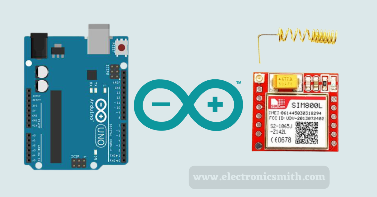
The SIM800L is a GSM module that can be used to send and receive SMS messages as well as make and receive calls. It can be controlled using a variety of microcontrollers, including Arduino. Using the SIM800L with an Arduino is relatively simple. The module can be powered using the Arduino’s power supply, and the Arduino can be used to control the module using software serial. In this article, we will see how to use the SIM800L module with Arduino for sending and receiving SMS and Calls.
SIM800L is a complete GSM module in an LGA type that can be used for GSM and GPRS applications. It is used in both GSM and GPRS modes. It has an integrated TCP/IP stack that can be used to connect to the Internet. The module works to send and receive SMS and calls. It can also be used to connect to the Internet.
Hardware overview
It has a small form factor and can be used in various applications. The module has a built-in antenna and can be used with various GSM networks.
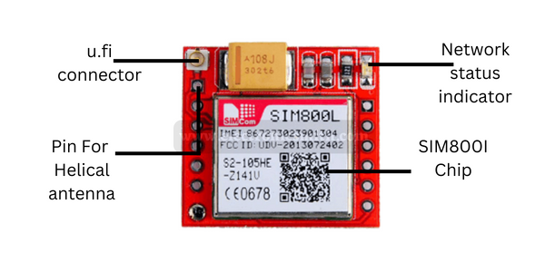
It has a four-pin interface that includes power, ground, RX, and TX. The module can be powered with a 3.3V or 5V power supply. An external antenna is needed for the module to be connected to the network. The module usually comes with a helical antenna that can be soldered onto the module. The board also features a U.FL connector in case you want to keep the antenna away from the board.
There’s a SIM socket on the back! Any 2G Micro SIM card will work perfectly. The correct direction to insert the SIM card is usually engraved on the surface of the SIM socket.

The SIM800L is a great option for anyone looking for a GSM module that is easy to use and has a wide range of features.
LED Status Indicators
On the top right of the SIM800L module is an LED that indicates the status of your cellular network. It blinks at different rates depending on which state it is in:
- The led is blinking continuously after 1 Second indicating the module is running but the connection to the cellular network has not yet been made.
- The LED blinking after 2 seconds indicates the GPRS data connection you requested is active.
- If the led blink after 3 Seconds indicates the module has made contact with the cellular network and can send/receive voice and SMS.
PinOut

The module consists of the given pins, and their information is as follows:
NET, which is used for connecting the antenna coming from the module.
VCC, which is the voltage supplier. The ideal working of VCC is done when the voltage is between 3.7 V to 4.4 V.
RST, which is known as a reset pin. And this is the pin used for the hard rest of the module.
RxD is known as the receiver. Its use includes communication and also for sending commands to the module.
TxD, known as the transmitter pin. Used for communication and for transmitting data to the Arduino.
GND is known as a ground pin. It is joined to the Arduino ground.
RING works as the indicator has a high pulse, but while receiving, it becomes low in terms of ms. It is used in the detection of received calls and SMS.
DTR works for sleep mode. The two modes are available, of which the high means the sleep mode enabled and communication disabled while the low means the sleep mode disabled and communication enabled.
MIC+, used as the microphone output also the MIC- is available, and the microphone pins are joined to these two available.
SPK+, similar to the MIC, consists of the SPK- and is known as the speaker interface. The pins of it can be joined here.
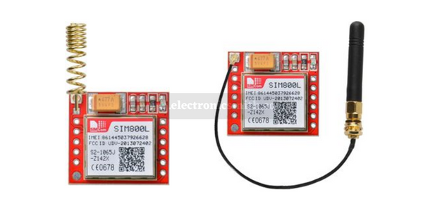
Selecting Antenna
An antenna is required to use the module for any type of voice or data communication. The first is a helical antenna that usually comes with the module and can be soldered directly onto the PCB. Another way is a 3dBi GSM antenna with a U.FL to SMA adapter that can be found online for less than $3. You can snap-fit this antenna into the small u.fl connector located on the top-left corner of the module.
Material required
| S. no. | Components | Quantity |
| 1. | Arduino board | 1 |
| 2. | GSM module | 1 |
| 7. | Arduino power supply | 1 |
| 9. | Jumper wires | 20 |
| 10. | Breadboard | 1 |
Circuit connection
From above the information about this must be clear. Now let’s know about the wiring of the hardware.
The power and ground pins are self-explanatory. The TX and RX pins are used for serial communication between the module and the Arduino. The RST pin is used to reset the module. The DTR, RTS, and CTS pins are used for flow control and are not required for this project.
- The first step is to connect the antenna to the module and insert the sim card.
- The second step is to connect the power and ground pins. The SIM800L module can be powered with 3.3V or 5V. We will be using 5V in this project.
- Next, connect the TX pin of the module to the RX pin of the Arduino and the RX pin of the module to the TX pin of the Arduino.
- Now, connect the RST pin of the module to the Arduino. This is optional but it’s a good idea to have a reset button for the module.
- Finally, connect the DTR, RTS, and CTS pins of the module to the Arduino. These are not required for this project but they can be used for flow control if needed.
Though several options are available for powering the module, the two used here are a battery and a bucks converter.
Arduino Code – Testing AT Commands
We will use the Serial Monitor to transmit AT instructions and communicate with the SIM800L module. The Arduino will be able to connect with the SIM800L module through the serial monitor thanks to the below-posted program. Connect your Arduino to your computer, build the following code, and upload it to your Arduino before we continue with the deep study of the code.
Make sure the “Both NL and CR” option is chosen once the Serial Monitor is open!
#include <SoftwareSerial.h>

//Create software serial object to communicate with SIM800L
SoftwareSerial mySerial(3, 2); //SIM800L Tx & Rx is connected to Arduino #3 & #2

void setup()
{
  //Begin serial communication with Arduino and Arduino IDE (Serial Monitor)
  Serial.begin(9600);

  //Begin serial communication with Arduino and SIM800L
  mySerial.begin(9600);

  Serial.println("Initializing...");
  delay(1000);

  mySerial.println("AT"); //Once the handshake test is successful, it will back to OK
  updateSerial();
  mySerial.println("AT+CSQ"); //Signal quality test, value range is 0-31 , 31 is the best
  updateSerial();
  mySerial.println("AT+CCID"); //Read SIM information to confirm whether the SIM is plugged
  updateSerial();
  mySerial.println("AT+CREG?"); //Check whether it has registered in the network
  updateSerial();
}

void loop()
{
  updateSerial();
}

void updateSerial()
{
  delay(500);
  while (Serial.available())
  {
    mySerial.write(Serial.read());//Forward what Serial received to Software Serial Port
  }
  while(mySerial.available())
  {
    Serial.write(mySerial.read());//Forward what Software Serial received to Serial Port
  }
}
Once you have uploaded the sketch, open the serial monitor at the baud rate of 9600. You should see the output below on the serial monitor.

AT Commands
You are now free to send commands such as the following through the Serial Monitor which give more information about network connection and battery status:
ATI – Returns the module name and revision.
AT+COPS? – Checks which network you are connected to, in our case Vodafone.
AT+COPS=? – Returns the list of operators present in the network.
AT+CBC – Returns Li-Po battery status. The second number is the battery level (in our case it is 93%) and the third number is the actual voltage in mV (in our case 3.877 V)
Arduino Code – Sending an SMS
#include <SoftwareSerial.h>

//Create software serial object to communicate with SIM800L
SoftwareSerial mySerial(3, 2); //SIM800L Tx & Rx is connected to Arduino #3 & #2

void setup()
{
  //Begin serial communication with Arduino and Arduino IDE (Serial Monitor)
  Serial.begin(9600);

  //Begin serial communication with Arduino and SIM800L
  mySerial.begin(9600);

  Serial.println("Initializing...");
  delay(1000);

  mySerial.println("AT"); //Once the handshake test is successful, it will back to OK
  updateSerial();

  mySerial.println("AT+CMGF=1"); // Configuring TEXT mode
  updateSerial();
 mySerial.println("AT+CMGS=\"+ZZxxxxxxxxxx\"");//change ZZ with country code and xxxxxxxxxxx with phone number to sms
  updateSerial();
  mySerial.print("Electronic smith | electronicsmith.com"); //text content
  updateSerial();
  mySerial.write(26);
}

void loop()
{
}

void updateSerial()
{
  delay(500);
  while (Serial.available())
  {
    mySerial.write(Serial.read());//Forward what Serial received to Software Serial Port
  }
  while(mySerial.available())
  {
    Serial.write(mySerial.read());//Forward what Software Serial received to Serial Port
  }
}
Arduino Code – Reading an SMS
This code turns ON or OFF LED, you can replace LED with a relay to control fans, bulbs, AC, or any heavy device.
#include <SoftwareSerial.h>

//Create software serial object to communicate with SIM800L
SoftwareSerial mySerial(3, 2); //SIM800L Tx & Rx is connected to Arduino #3 & #2

void setup()
{
  //Begin serial communication with Arduino and Arduino IDE (Serial Monitor)
  Serial.begin(9600);

  //Begin serial communication with Arduino and SIM800L
  mySerial.begin(9600);

  Serial.println("Initializing...");
  delay(1000);

  mySerial.println("AT"); //Once the handshake test is successful, it will back to OK
  updateSerial();

  mySerial.println("AT+CMGF=1"); // Configuring TEXT mode
  updateSerial();
  mySerial.println("AT+CNMI=1,2,0,0,0"); // Decides how newly arrived SMS messages should be handled
  updateSerial();
}

void loop()
{
  updateSerial();
}

void updateSerial()
{
  delay(500);
  while (Serial.available())
  {
    mySerial.write(Serial.read());//Forward what Serial received to Software Serial Port
  }
  while(mySerial.available())
  {
    Serial.write(mySerial.read());//Forward what Software Serial received to Serial Port
  }
}
Arduino Code – Making a Call
#include <SoftwareSerial.h>

//Create software serial object to communicate with SIM800L
SoftwareSerial mySerial(3, 2); //SIM800L Tx & Rx is connected to Arduino #3 & #2

void setup()
{
  //Begin serial communication with Arduino and Arduino IDE (Serial Monitor)
  Serial.begin(9600);

  //Begin serial communication with Arduino and SIM800L
  mySerial.begin(9600);

  Serial.println("Initializing...");
  delay(1000);

  mySerial.println("AT"); //Once the handshake test is successful, i t will back to OK
  updateSerial();

 mySerial.println("ATD+ +ZZxxxxxxxxxx;"); //  change ZZ with country code and xxxxxxxxxxx with phone number to dial
  updateSerial();
  delay(20000); // wait for 20 seconds...
  mySerial.println("ATH"); //hang up
  updateSerial();
}

void loop()
{
}

void updateSerial()
{
  delay(500);
  while (Serial.available())
  {
    mySerial.write(Serial.read());//Forward what Serial received to Software Serial Port
  }
  while(mySerial.available())
  {
    Serial.write(mySerial.read());//Forward what Software Serial received to Serial Port
  }
}
Arduino Code – Receiving a Call
The following AT commands can be used to accept or hang up the call:
ATA – Accepts incoming call.
ATH – Hangs up the call. On hanging up the incoming call, we get NO CARRIER on the serial monitor indicating that the call could not be connected.
#include <SoftwareSerial.h>

//Create software serial object to communicate with SIM800L
SoftwareSerial mySerial(3, 2); //SIM800L Tx & Rx is connected to Arduino #3 & #2

void setup()
{
  //Begin serial communication with Arduino and Arduino IDE (Serial Monitor)
  Serial.begin(9600);

  //Begin serial communication with Arduino and SIM800L
  mySerial.begin(9600);

  Serial.println("Initializing...");
}

void loop()
{
  updateSerial();
}

void updateSerial()
{
  delay(500);
  while (Serial.available())
  {
    mySerial.write(Serial.read());//Forward what Serial received to Software Serial Port
  }
  while(mySerial.available())
  {
    Serial.write(mySerial.read());//Forward what Software Serial received to Serial Port
  }
}
2 thoughts on “Send Receive SMS & Call with SIM800L GSM Module & Arduino”