
This project illustrates how to construct a small DC voltmeter (0-25V) with an Arduino and a voltage sensor module. The circuit takes input voltage through a resistive divider network, shows real-time readings on a display, and gives precise measurements for power supplies and batteries. Suitable for electronics testing, battery testing, and voltage fault detection, this handheld form factor is low-cost, easy to implement, and configurable for sophisticated applications such as data logging or wireless telemetry.
Materials Required:
| Component | Quantity |
|---|---|
| Arduino Nano Board | 1 |
| 0-25V Voltage Sensor Module | 1 |
| A Display | 1 |
| Jumper Wires | As needed |
| Breadboard | 1 |
Working

This voltage sensor uses a basic voltage divider circuit to safely read higher voltages on an Arduino. Two resistors (30kΩ and 7.5kΩ) within the module create a fixed 5:1 ratio division, so the input voltage is divided down by five before it ever reaches your Arduino’s analog pin. For example, when reading a 10V source, the sensor only puts 2V onto the Arduino – safely within its 5V limit. The Arduino then converts this divided voltage with its analog-to-digital converter and multiplies it back out by five in code to display the actual input voltage. This clever trick allows you to read up to 25V while keeping your microcontroller safe from harm. The module is reasonably accurate enough for most basic measurements, but very small voltages below 0.5V may be less accurate due to the constraints of the Arduino’s analog resolution. It’s a convenient, low-cost solution to battery monitoring, power supply testing, and other voltage measurement tasks in DIY electronics projects.
On Board Components

Resistive Voltage Divider Network
The core of the module consists of two 30kΩ (R1) and 7.5kΩ (R2) precision resistor pairs that are built into a voltage divider circuit. This particular ratio provides an accurate 5:1 voltage drop, enabling voltages up to 25V to be measured safely while allowing a maximum of 5V to be passed through to avoid burning the microcontroller’s analog input pins. The resistors are usually 1% tolerance metal film types for improved voltage division accuracy.
High-Voltage Screw Terminals
The module has sturdy screw terminals with prominent red (VCC) and black (GND) labels for convenient high-voltage input wire connection. The terminals can accommodate wire gauges up to 18AWG and are safety-engineered with elevated barriers to prevent accidental short circuits when working with higher voltages.
3 Pin Output Header
A generic 3 pin male header is the interface of the microcontroller, which is composed of:
+
pin for module power (connected to 5V or 3.3V)
-\ ground pin for attaching
S pin (signal output) that supplies the derived voltage to the analog input pin of the microcontroller
Signal Conditioning Parts
The board includes a 0.1µF ceramic capacitor near the output to filter out high-frequency noise and provide a cleaner analog voltage to the microcontroller. A few models include a small protection diode to prevent reverse polarity voltage damage and transient voltage spikes.
Power Indicator LED
Red surface-mount LED and current-limiting resistor are used as visual indication of power connection. LED glows under any situation in which there is input voltage at the input terminals.
Pin out:
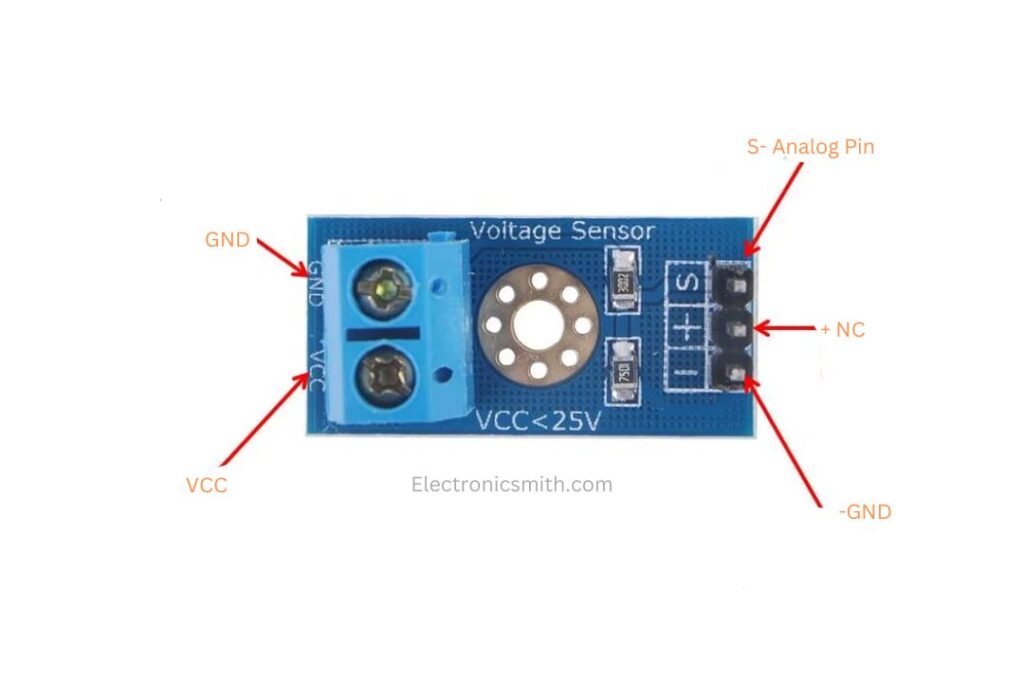
VCC
This pin is the positive supply voltage terminal from the outside voltage supply. This pin will have a voltage input of 0 to 25V.
GND
This is the negative terminal of the external power source. It is the path for the return of electric current in the circuit.
S
The signal pin which you have to connect to an analog input pin of the Arduino. It is used to send analog signals to the microcontroller.
+
This pin is not internally connected (NC). It is not used for any working function within the circuit and might not be connected.
−
This is a second ground connection that has to be connected to the Arduino GND pin. It offers a common reference voltage point between the Arduino and the sensor.
Voltage Sensor Module: Construction & Design
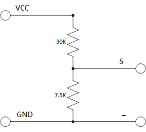
The Voltage Sensor Module is really a voltage divider circuit, constructed using two resistors of 30KΩ and 7.5KΩ. This is a 5:1 voltage divider, meaning that the input voltage is divided by a factor of five at the output. Thus, any input voltage is decreased by a factor of 5. This enables higher voltages to be safely read by a microcontroller. The internal circuit diagram of the voltage sensor module shows this arrangement.
Since analog input pins in an Arduino are capable of reading voltages of up to 5V, this module will be able to read input voltages up to 25V safely. In case your microcontroller has an analog reference voltage of 3.3V (say certain ESP32 or STM32 boards), input voltage will have to be kept limited to 3.3V × 5 = 16.5V.
AVR-based Arduinos like Uno or Nano utilize a 10-bit ADC. This gives a resolution of 0.00489V per step (calculated as 5V / 1023). When the voltage divider factor is taken into account, the minimum input voltage that can be read is 0.00489V × 5 = 0.02445V.
Connecting the 0–25V DC Voltage Sensor Module to Arduino To link the module to Arduino, the Signal (S) pin is linked to A0, and the negative (-) pin to GND of Arduino. The procedure is simple, and the connections are minimal.
Connecting 0–25V DC Voltage Sensor Module to Arduino
To connect Arduino to the module, connect A0 to Signal (S), and GND of Arduino to the negative (-) pin. The installation process is easy and the wiring process is minimal.
Arduino Code for Serial Monitor Display
Here is the code to read the voltage and show it through the Serial Monitor:
#define ANALOG_IN_PIN A0

float adc_voltage = 0.0;
float in_voltage = 0.0;

float R1 = 30000.0; // 30KΩ
float R2 = 7500.0;  // 7.5KΩ

float ref_voltage = 5.0;
int adc_value = 0;

void setup() {
  Serial.begin(9600);
  Serial.println("DC Voltage Test");
}

void loop() {
  adc_value = analogRead(ANALOG_IN_PIN);
  adc_voltage = (adc_value * ref_voltage) / 1024.0;
  in_voltage = adc_voltage / (R2 / (R1 + R2));

  Serial.print("Input Voltage = ");
  Serial.println(in_voltage, 2);

  delay(500);
}
Arduino Code for Voltage Measurement (Serial Monitor Output)
#define ANALOG_IN_PIN A0

float adc_voltage = 0.0;
float in_voltage = 0.0;

float R1 = 30000.0; // Resistor R1 = 30KΩ
float R2 = 7500.0;  // Resistor R2 = 7.5KΩ

float ref_voltage = 5.0; // Reference voltage for ADC
int adc_value = 0;

void setup() {
  Serial.begin(9600);
  Serial.println("DC Voltage Test");
}

void loop() {
  // Read analog value
  adc_value = analogRead(ANALOG_IN_PIN);

  // Convert ADC value to voltage
  adc_voltage = (adc_value * ref_voltage) / 1024.0;

  // Convert to actual input voltage using divider formula
  in_voltage = adc_voltage / (R2 / (R1 + R2));

  // Display voltage
  Serial.print("Input Voltage = ");
  Serial.println(in_voltage, 2);

  delay(500); // Wait half a second
}
Testing and Validation
To validate the correct testing of the sensor, it was tested under various power sources:
A 3.7V Lithium-Ion battery provided a correct value, which is its precise voltage.
9V battery also gave a good performance.
When plugged into a dead 3S Lithium-Ion battery, the reading was approximately 5V, as predicted.
These tests confirmed the consistency of the sensor across a range of voltage levels.
Conclusion
This project demonstrates how to measure voltages of up to 25V DC safely using an Arduino and a simple voltage divider-based sensor module. By means of resistor division of the input voltage, the module gives safe and accurate readings within the Arduino 5V input range.
With a sensitivity of as high as 0.024V, this setup is ideally suited for applications such as battery monitoring, power supply testing, and simple voltage diagnostics on electronics projects. Its low cost and simplicity make it an accessible tool for hobbyists and beginners to use.