
In modern electronic systems, a semiconductor diode bridge, commonly referred to as a bridge rectifier is a crucial component. Found in everything from household appliances to industrial equipment like motor controllers and welding devices, it performs the essential job of converting alternating current from a power source into direct current to power internal circuits and components.
Overview
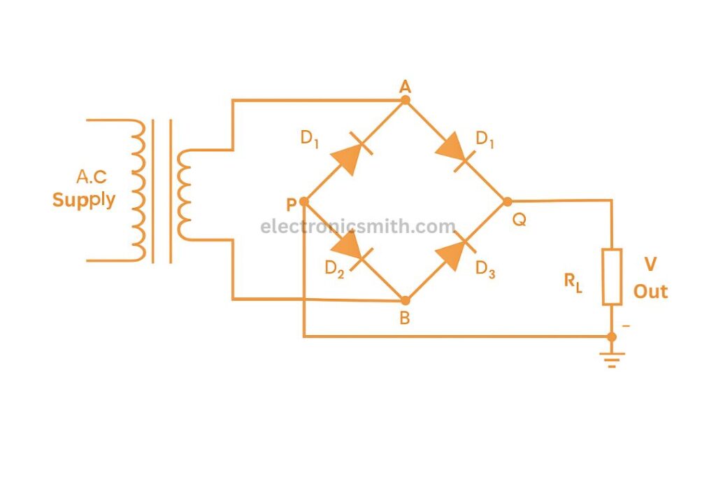
A bridge rectifier is an electrical circuit that uses four diodes arranged in a bridge configuration to convert AC input into DC output. Unlike half-wave rectifiers or center-tapped full-wave rectifiers, the bridge rectifier doesn’t require a center-tapped transformer, which significantly reduces cost and size. Bridge rectifiers are used in a wide range of devices from switch-mode power supplies and linear power supplies to radios and electric welding equipment. Its ability to utilize both halves of the AC signal makes it more efficient than simpler rectifier types.
Circuit Diagram:
Working Principle:
The bridge rectifier utilizes the unidirectional conductivity of diodes to ensure that current through the load resistor always flows in the same direction. On both positive and negative half cycles of AC input, the output across the load remains positive, giving a full-wave rectified output. This makes the bridge configuration especially effective for applications requiring continuous DC power.
Construction and Working:
A standard bridge rectifier consists of:
- Four diodes (D1, D2, D3, and D4)
- An AC input
- A load resistor (RL)
- Often, a smoothing capacitor is used for filtering
Positive Half Cycle
When the AC input is in its positive half cycle:
- Diodes D1 and D3 conduct (forward-biased)
- Diodes D2 and D4 are non-conductive (reverse-biased)
- Current flows through the load resistor RL in one direction
Negative Half Cycle
During the negative half cycle:
- Diodes D2 and D4 conduct
- Diodes D1 and D3 are non-conductive
- Again, current flows through the load RL in the same direction
The Output
To convert the pulsed DC into a smoother output, a filter capacitor is connected across the output terminals. This capacitor:
- Charges when the voltage rises
- Discharges when the voltage drops
- Helps in reducing the ripple in the output waveform
Applications:
Home appliances (TVs, washing machines, microwaves)
Motor controllers
Electric welding equipment
Modulation and communication devices
Power supplies for electronic circuits
Advantages:
Higher Efficiency:
Utilizes both halves of the AC input waveform
No Center Tap Needed:
Simplifies transformer design and reduces cost
Smoother Output:
Especially when combined with filter capacitors
Compact Design:
Suitable for modern miniaturized electronics
Conclusion:
A bridge rectifier remains an essential component in the world of electronics, offering an effective and practical way to convert AC into DC. From powering small household gadgets to operating industrial machines, its applications are vast. By eliminating the need for complex transformer setups, bridge rectifiers have made modern electronics more compact, efficient, and affordable.