Hey! If you’re attempting to make a basic motion sensor project with an Arduino and a PIR sensor, you’re on the right site. Throughout this tutorial, I’ll take you through how to assemble the circuit, sensor calibration, code, and test your prototype. If you’re new to this or simply need a nice little project to tinker with, I hope this tutorial assists you in getting started. Let’s go!
Materials Required:
| Components | Quantity |
|---|---|
| ELEGOO UNO R3 | 1 |
| PIR Motion Sensor (HC-SR501) | 1 |
| LED | 1 |
| Male-to-Female Jumper Wires | 3 |
| Breadboard | 1 |
| Resistor (220Ω) | 1 |
| USB Cable | 1 |
| Computer | 1 |
| Arduino IDE | 1 |
Working of Sensor:
PIR stands for Pyroelectric Infrared Sensor or sometimes refered to as a Passive Infrared Sensor. It is an electronic sensor that works by detecting changes in infrared light over a certain distance and produces an electrical signal as its output. This type of sensor is capable of sensing any object that emits infrared radiation, including humans or animals, as long as it is within its detection range. If the object moves closer or further away within the sensor’s range, it can pick up the change and respond accordingly.
Pinout:
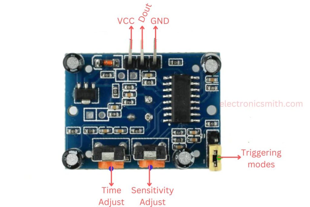
Vcc:
The input voltage is generally +5V in the majority of applications, but it can be anywhere from 4.5V to 12V.
High/Low Output (Dout):
This pin outputs a digital pulse. It is high (3.3V) when motion is detected and low (0V) when there is no motion.
Ground (GND):
This pin is grounded to the circuit to make sure that the electrical connection is established.
Trigger Modes in PIR Sensor:
The PIR sensor operates in two different trigger modes: Non-Repeat Mode and Repeat Trigger Mode. The selection between these two modes can be done by adjusting the jumper located at the corner of the sensor module.
Non-Repeat Mode:
In this mode, when the PIR sensor senses motion, the output signal becomes HIGH for a set time and then turns LOW automatically after that time, irrespective of any subsequent motion.
For example, if the output becomes HIGH for 10 seconds, it will revert to LOW as soon as this time has elapsed, even if the motion continues.
Repeat Trigger Mode:
When it is configured in this mode, the output will be HIGH as long as the sensor is continuously sensing motion. Whether it is a single person in motion or multiple people within range, the output will only switch LOW once no motion is detected anymore.
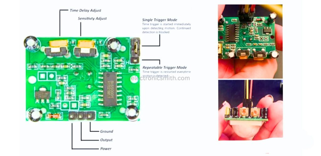
Block Time:
Block time refers to a brief time when the PIR sensor is insensitive to any movement, basically keeping it inactive for some time. The time is generally about 3 seconds. As soon as the time elapses, the sensor resets and can detect movement once again.
Adjustment of Delay Time:
A potentiometer is built on the module, enabling us to set how long the output signal stays in HIGH state upon sensing motion. The delay value can be between 5 seconds to 5 minutes, subject to the task at hand.
Sensitivity Adjustment:
Another potentiometer can be used to change the sensitivity of the PIR sensor. The range to detect can be adjusted between 3 meters to 7 meters, perpendicular to the sensor. But the sensor becomes less sensitive while detecting movement at an angle compared to straight in front. The detection zone is a conical section with about 110 degrees.
Making:
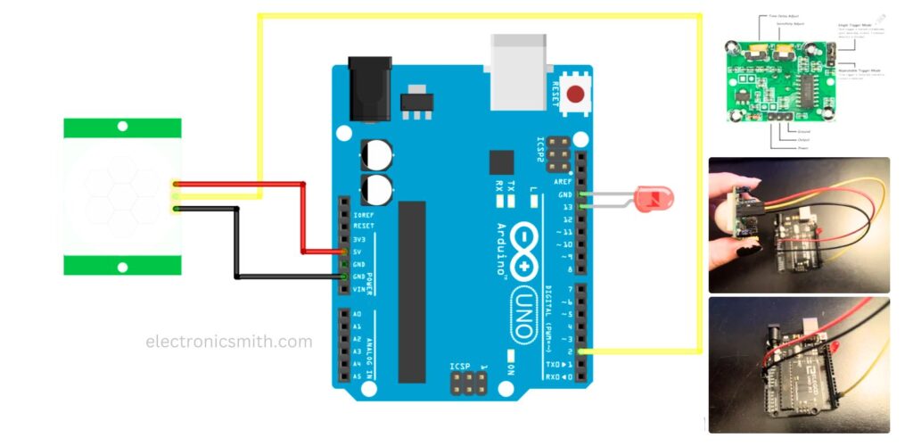
Step 1: Installation of the Circuit
I have added a photograph and file of the Fritzing diagram for reference. I’ve taken this from an Arduino Project Hub tutorial in order to grasp the broad concept of programming a PIR sensor.
For this prototype, I left the LED on the UNO on Pin 13 and ground (Remember: Short leg in ground; long leg in Pin 13).
To interconnect the PIR Sensor to the UNO, I have utilized the male to female jumpers. Power is where 5V is linked; Output is linked to Pin 2; Ground is linked to Ground (See PIR Sensor Diagram).
IMPORTANT NOTE: Make sure you have the power and ground wires properly connected to the sensor! I mixed up those two my first time through with the sensor. The second picture is a picture of the entire components of the PIR sensor.
Step 2: Personalizing the PIR Sensor
The PIR sensor is adjustable by hand if you look at the back. I needed to do some minor tweaks to get the sensor more sensitive before I pushed too far on the code.
The first part is changing the Trigger Mode from low to high. It is a tiny jumper at the top right-hand side of the sensor with L and H labeled (refer to the PIR diagram). Reason: If it was set on Single Trigger Mode (Low), the LED would switch off within a few seconds even when the motion is continuous. On Repeatable Trigger Mode (High), the LED will remain on with continuous motion and switch off when there is no motion.
Next, adjust the Time Delay to the lowest setting. I want the sensor to react as fast as possible to when there is no motion. The lower the setting; the faster the light will be turned off. Keep in mind that Clockwise to raise; Counter-clockwise to decrease. And, the lowest setting will still have approximately a three-second delay.
Step 3: Simple Test of the Sensor
After all that setup, I used the code from the Arduino Project Hub tutorial to test whether the sensor is in proper working condition.
When I run the code, I give the sensor 15-30 seconds to come up before I try motion.
The most important thing to be considered in this test is:
Does the sensor react when you wave a hand in front of it? (If not, check to see if the sensor is properly connected or the sensitivity is set too low)
Does the LED stay on if you keep waving your hand in front of the sensor? (If not, check if the jumper is high for Repeatable Trigger Mode)
Is the time delay for the LED a few seconds when no motion is detected? (If not, set Time Delay to the lowest setting)
Important Note: The LED light will stay on until the sensor is complete with calibrating, but the only time that the LED came on when the uploaded script was when I had the power and ground on the wrong pins. With my sensor, when connected correctly, the LED will stay off when uploading the script, and was the only time that it would detect motion properly.
/*
 * PIR_HCSR501
 * modified on 5 Feb 2019
 * by Saeed Hosseini @ ElectroPeak
 * https://electropeak.com/learn/guides/
 */

int ledPin = 13;    // LED
int pirPin = 2;     // PIR Out pin
int pirStat = 0;    // PIR status

void setup() {
    pinMode(ledPin, OUTPUT);
    pinMode(pirPin, INPUT);
    Serial.begin(9600);
}

void loop() {
    pirStat = digitalRead(pirPin);
    if (pirStat == HIGH) {            // if motion detected
        digitalWrite(ledPin, HIGH);  // turn LED ON
        Serial.println("Hey I got you!!!");
    }
    else {
        digitalWrite(ledPin, LOW);   // turn LED OFF if we have no motion
    }
}
Step 4: Installing the Final Code
Once I was able to test my motion sensor, I wanted to try to take the last code and make it a little more complicated and blink quickly when it senses movement. I also did not like what the Serial Monitor was being programmed to print, so I will make a new version of that as well. (Copy of final code in this step)
What was launched:
Blink Command
New Serial Script Updated Version
The blink command is turning the LED on and off with the “delay” command. It has a delay that works on the millisecond (Example: 1000 m/s = 1 second). I did not prefer the one-second delay so I reduced the time to 100 m/s.
The serial monitor script was slightly more time-consuming to write in the setup. I needed to have a message that appears when the serial monitor is activated in the setup. I also added a message that updates with the continuous state of the sensor. When writing a serial monitor, don’t forget the commands “Serial.begin(9600)”, “Serial.print()”, and “Serial.println()”.
Note: I did come across one example code where there is an option of having the monitor respond only to the output change and not the state change. If you wish to do that, Ada Fruit has a replica of their code in this article. It tidies up the serial monitor, but it does mean adding extra variables and if statements. Because of that, I left it out of this tutorial so that others can easily follow it. But for future projects, I would suggest adding this into the code.
int ledPin = 13;                // LED
int pirPin = 2;                 // PIR Out pin
int pirStat = 0;                // PIR status

void setup() {
  pinMode(ledPin, OUTPUT);      // declare LED as output
  pinMode(pirPin, INPUT);       // declare sensor as input
  Serial.begin(9600);
  Serial.println("Serial Monitor connected");
  delay(1000);
  Serial.print(".");
  delay(500);
  Serial.print(".");
  delay(500);
  Serial.print(".");
  delay(500);
  Serial.println("Please let your sensor calibrate");
  delay(1000);
  Serial.println("for 15 to 30 seconds before testing");
  delay(1000);
  Serial.print(".");
  delay(500);
  Serial.print(".");
  delay(500);
  Serial.print(".");
  delay(500);
}

void loop() {
  pirStat = digitalRead(pirPin);
  if (pirStat == HIGH) {        // if motion detected
    Serial.println("Motion Detected!");
    digitalWrite(ledPin, HIGH); // turn LED ON
    delay(1000);                // wait for a second
    digitalWrite(ledPin, LOW);  // turn LED OFF
    delay(1000);                // wait for a second
  } else {
    digitalWrite(ledPin, LOW);  // LED stays off if no motion detected
    Serial.println("No Motion Detected!");
  }
}
Step 5: Testing the Prototype
After compiling all the steps, I made a working motion sensor prototype. The best part about the last code is that I can see what the sensor is picking up in the serial monitor, and I can tinker with anything on the sensor without having to change anything on the code. I believe that I am clearer on how the PIR sensor works. I hope that others will find this tutorial helpful.