We will be making a power supply, which is very necessary for a circuit to work as it provides the necessary voltage to the circuits for its operations. Voltage and current are just like water pressure and water rate respectively. Most electronics need a specific voltage and current to function, and in this tutorial, we will focus on creating a 5V power supply.
Creating 5V battery:
We will start with a battery or wall adapter and make use of a regulator, specifically the LM7805. This regulator converts raw voltage to a stable one at 5V. So long as its input is just a bit higher – in our case, this is at least 7V – the regulator supplies a steady voltage. Okay, so let us begin with a simple and functional 5V power supply!
We already have a guide 12v power supply you can use it as a source instead of a battery.
Materials Required:
| Material | Quantity | Description |
|---|---|---|
| LM7805 Voltage Regulator | 1 | 3-pin linear voltage regulator for 5V output |
| 10 µF Capacitors | 2 | Electrolytic capacitors for filtering |
| 0.1 µF Capacitors | 2 | Ceramic capacitors (non-polarized) for noise reduction |
| Red LED | 1 | 5mm red LED for power indication |
| 330 Ohm Resistor | 1 | Current-limiting resistor for LED |
| Breadboard | 1 | Prototyping tool for circuit assembly |
| 9V Battery | 1 | Power source for the circuit |
| Battery Connector | 1 | Connector with soldered headers for breadboard use |
| Jumper Wires | 5 | Pre-cut wires for circuit connections |
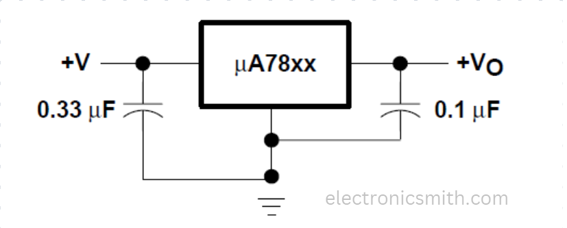
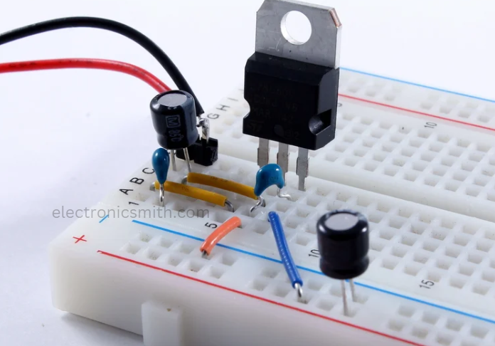
Step 1: LEDs and Capacitors
Add a 0.33 µF capacitor to the input and a 0.1 µF capacitor to the output of the regulator for noise filtering. Larger capacitors will provide more stability and a red LED with a current-limiting resistor serves as a power indicator.
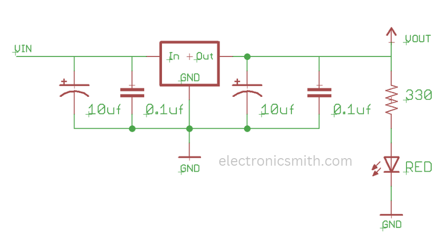
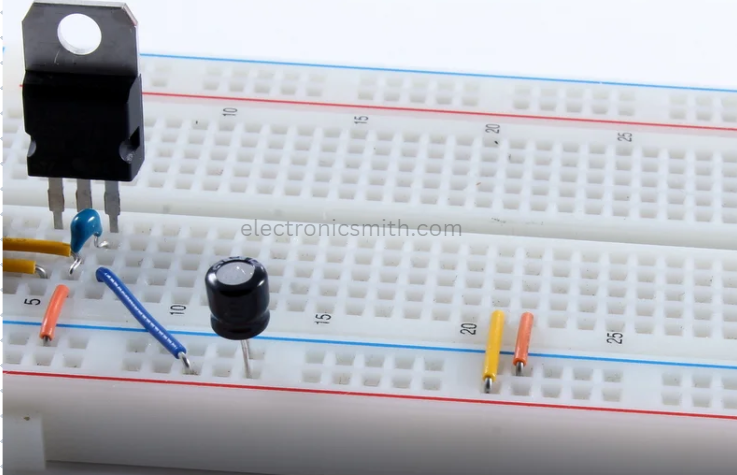
Step 2: Better Circuit
Update the circuit to 4 capacitors instead of using 2. Add in the LED with a 330-ohm resistor on it so it does not burn out. The resistor size is calculated using V=IR.
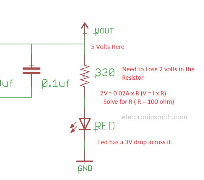
Step 3: 330 Ohm Resistor
The LED is kept bright while the battery life is conserved by using a 330-ohm resistor rather than a 100-ohm resistor for max brightness.
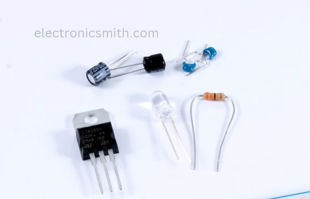
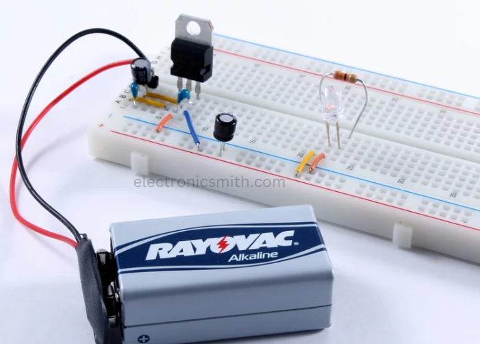
Step 4: What You’ll Need
The components include an LM7805 regulator, two 10 µF capacitors, two 0.1 µF capacitors, an LED, a 330-ohm resistor, a breadboard, a 9V battery, and a connector.
Step 5: Breadboarding
Prototype the circuit using a breadboard; it comes pre-wired with rows and columns that simplify the placing of components.
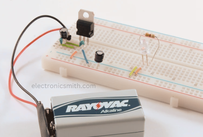
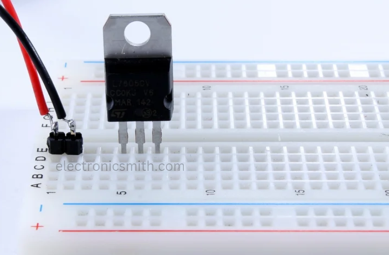
Step 6: Continued Breadboarding.
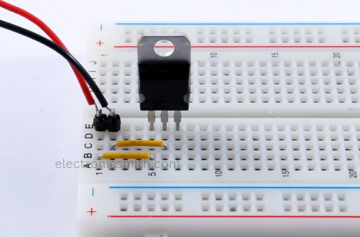
Position the battery connector and regulator onto the breadboard. The metal strips of the breadboard hold components in place and facilitate connections.
Step 7: Wiring Wire the regulator:
pin 1 is the input, pin 3 the output, and pin 2 is ground. Connect the battery to the regulator’s input.
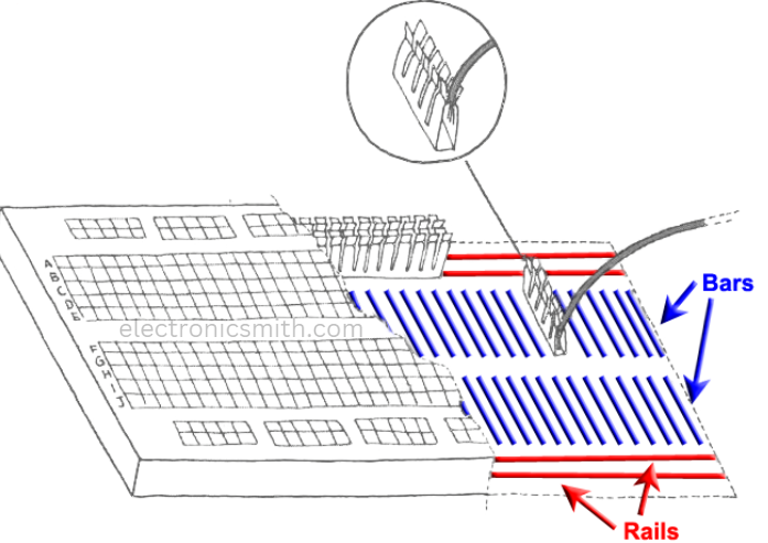
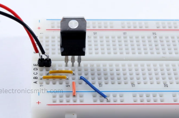
Step 8: Rails
Connect the regulator’s output to the breadboard’s power rails to distribute 5V throughout the circuit.
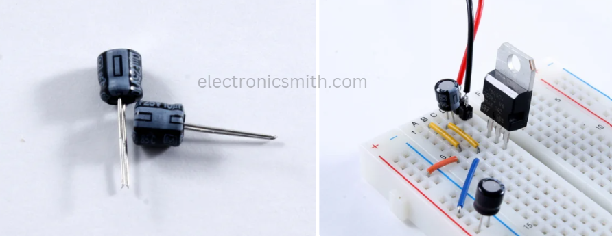
Step 9: Filter Capacitors
Connect the capacitors polarized; both 10 µF connected with the white stripe grounded.
Step 10: Capacitors
Connect input and output capacitors to the breadboard. Make sure polarized capacitors are polarized.
Step 11: 0.1µF Capacitors:
Attach the non-polarized 0.1 µF capacitors to further reduce noise in the circuit.
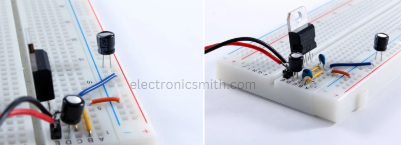
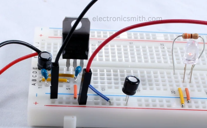
Step 12: Complete Regulator Circuit
The regulator circuit is complete. Now, add the power LED to indicate when the supply is on.
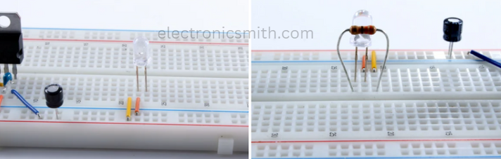
Step 13: Power Light
Connect the LED’s anode to the 5V output and cathode to ground with a resistor in series to protect the LED.
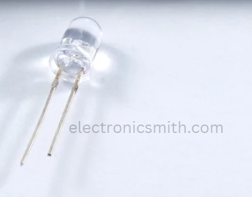
Step 14: 5mm Red LED
Connect the longer side leg of LED, which is the anode, to the plus end. The shorter one connects to the negative.
Step 15: LEDs Wired
Connect the LED cathode to the negative rail and its anode to the 5V rail via the resistor.
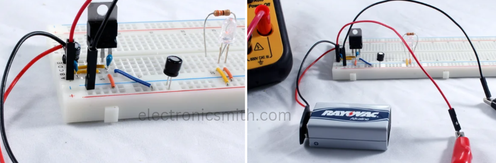
Step 16: Test
Insert the battery and the LED should illuminate to prove that the circuit works.
Step 17: Multimeter Connection
Using a multimeter in parallel, measure the voltage of the circuit. Add jumper wires to the breadboard for testing.
Step 18: Battery Voltage
Use the multimeter in DC mode to check the voltage of the battery. A new 9V battery should read slightly above 9 volts.
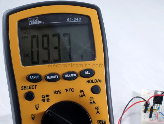
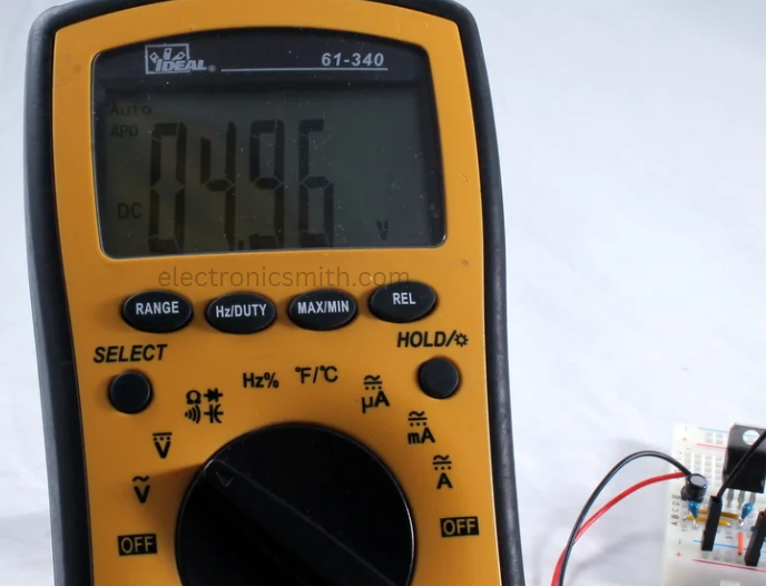
Step 19 Measure the output
Move the jumper wire to the regulator’s output rail and measure the output voltage.
Step 20: Conclusion
The circuit produces a 4.96 volts power, ready to power your circuit with up to 750 mA!
Frequently Asked Questions:
1. Why do I need capacitors in the circuit?
Capacitors filter out noise and stabilize the input and output voltages, ensuring a clean power supply for the circuit.
2. Why use a 330-ohm resistor with the LED?
The resistor limits the current through the LED preventing it from burning out while still keeping it bright enough.
3. Can I use a battery with less than 7 volts?
No, the LM7805 requires an input voltage at least 2 volts higher than the desired output (5V), so a 9V battery is ideal.
1 thought on “How to Make 5V Power Supply”