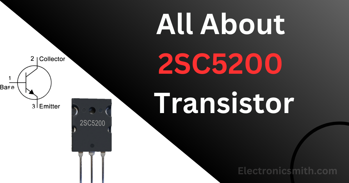
The 2SC5200 is a high-performance power transistor, commonly used in power amplifier output stages, especially in high-fidelity audio systems. Designed with a triple-diffused silicon structure, it operates reliably at high currents and voltages, making it suitable for both audio frequency and switching applications.
Overview
The 2SC5200 is a high-power NPN bipolar junction transistor commonly used in audio frequency (AF) amplifiers and high-power amplifier circuits. It serves as a replacement for the TTA5200 and is available in the TO-264 package made of epoxy and plastic materials. With a collector-emitter voltage (V<sub>CE</sub>) of 230V and a collector current of 30A, it is ideal for applications that require high current gain and large power dissipation. The transistor is frequently used in televisions, mobile devices, industrial systems, and flip-flop circuits. To avoid thermal damage during high-frequency switching operations, the 2SC5200 is typically used in conjunction with heat sinks. In many Class B amplifier designs, it is paired with its complementary PNP counterpart, the 2SA1943, in push-pull configurations, enabling efficient and powerful audio output.
Pin Out:
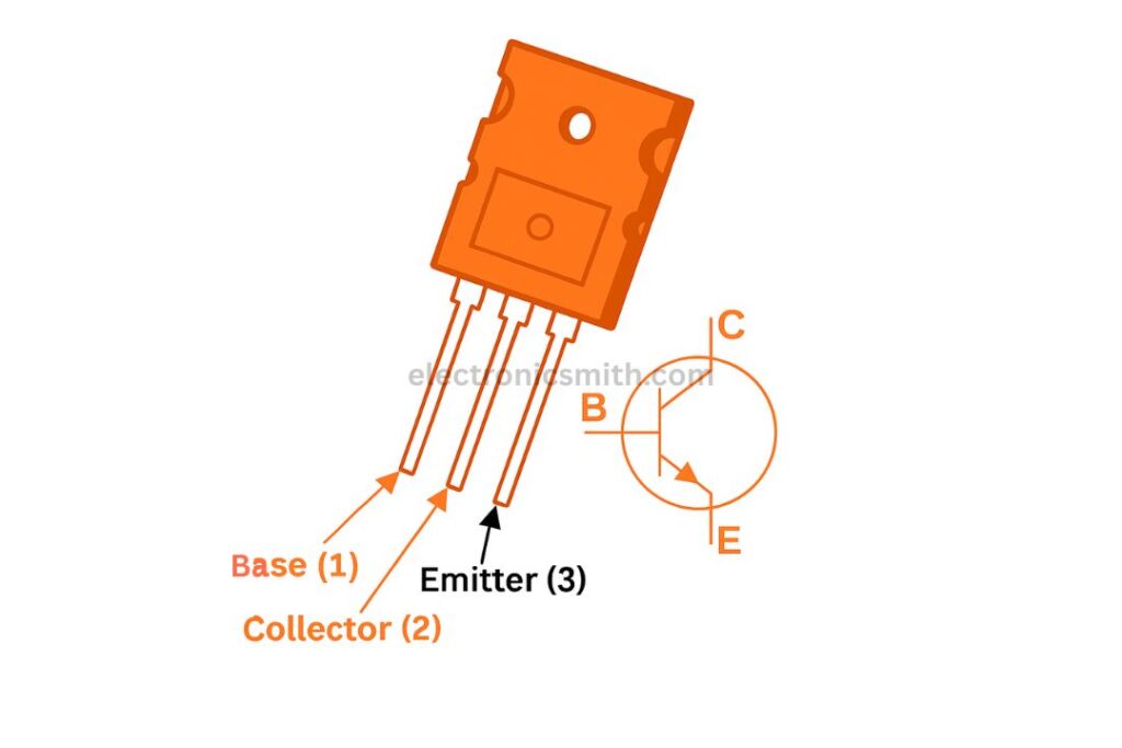
- Pin 1 (Base): Controls the transistor’s biasing and is responsible for switching it ON or OFF.
- Pin 2 (Collector): Receives current, usually from the load.
- Pin 3 (Emitter): Outputs current to ground or the circuit’s return path.
Equivalent & Complementary Transistors
Equivalents: 2SC5242, 2SD1313, 2SC3320, FJL4315
Replacements: MJL3281A, KTC5242, TTC5200, MJL13002A
Complementary Transistor: 2SA1943
Circuit Operation:
Audio signals from a smartphone or computer are fed into the amplifier through the audio jack. A 10K potentiometer adjusts the input signal strength. The 220µF capacitor filters out any DC component, allowing only the AC signal to reach the transistor base. The 2SC5200 then amplifies this signal, sending the output from the collector to the speaker. The negative speaker terminal connects to the collector, and the positive terminal connects to the power supply. A heat sink is recommended to prevent overheating.
2SC5200 Transistor Datasheet
| Parameter | Symbol | Rating | Unit |
|---|---|---|---|
| Collector–Base Voltage | V<sub>CBO</sub> | 230 | V |
| Collector–Emitter Voltage | V<sub>CEO</sub> | 230 | V |
| Emitter–Base Voltage | V<sub>EBO</sub> | 5 | V |
| Collector Current (Continuous) | I<sub>C</sub> | 15 | A |
| Base Current | I<sub>B</sub> | 1.5 | A |
| Collector Power Dissipation | P<sub>C</sub> | 150 | W |
| Junction Temperature | T<sub>j</sub> | 150 | °C |
| Storage Temperature Range | T<sub>stg</sub> | –55 to +150 | °C |
Electrical Characteristics:
| Parameter | Symbol | Test Conditions | Min | Typ | Max | Unit |
|---|---|---|---|---|---|---|
| Collector Cutoff Current | ICBO | VCB = 230V, IE = 0 | – | – | 5.0 | µA |
| Emitter Cutoff Current | IEBO | VEB = 5V, IC = 0 | – | – | 5.0 | µA |
| Collector-Emitter Breakdown Voltage | V(BR)CEO | IC = 50 mA, IB = 0 | 230 | – | – | V |
| DC Current Gain | hFE (1) | VCE = 5V, IC = 1A | 55 | – | 160 | – |
| DC Current Gain | hFE (2) | VCE = 5V, IC = 7A | 35 | 60 | – | – |
| Collector-Emitter Saturation Voltage | VCE(sat) | IC = 8A, IB = 0.8A | – | 0.4 | 3.0 | V |
| Base–Emitter Voltage | VBE | VCE = 5V, IC = 7A | – | 1.0 | 1.5 | V |
| Transition Frequency | fT | VCE = 5V, IC = 1A | – | 30 | – | MHz |
| Collector Output Capacitance | Cob | VCB = 10V, IE = 0, f = 1 MHz | – | 200 | – | pF |
Conclusion:
The 2SC5200 transistor is a robust, high-performance component ideal for high-fidelity audio applications and high-power switching circuits. With excellent gain, power dissipation, and thermal characteristics, it continues to be a favorite among designers and hobbyists alike. For detailed performance parameters, always refer to the official 2SC5200 datasheet when integrating it into your circuit designs.