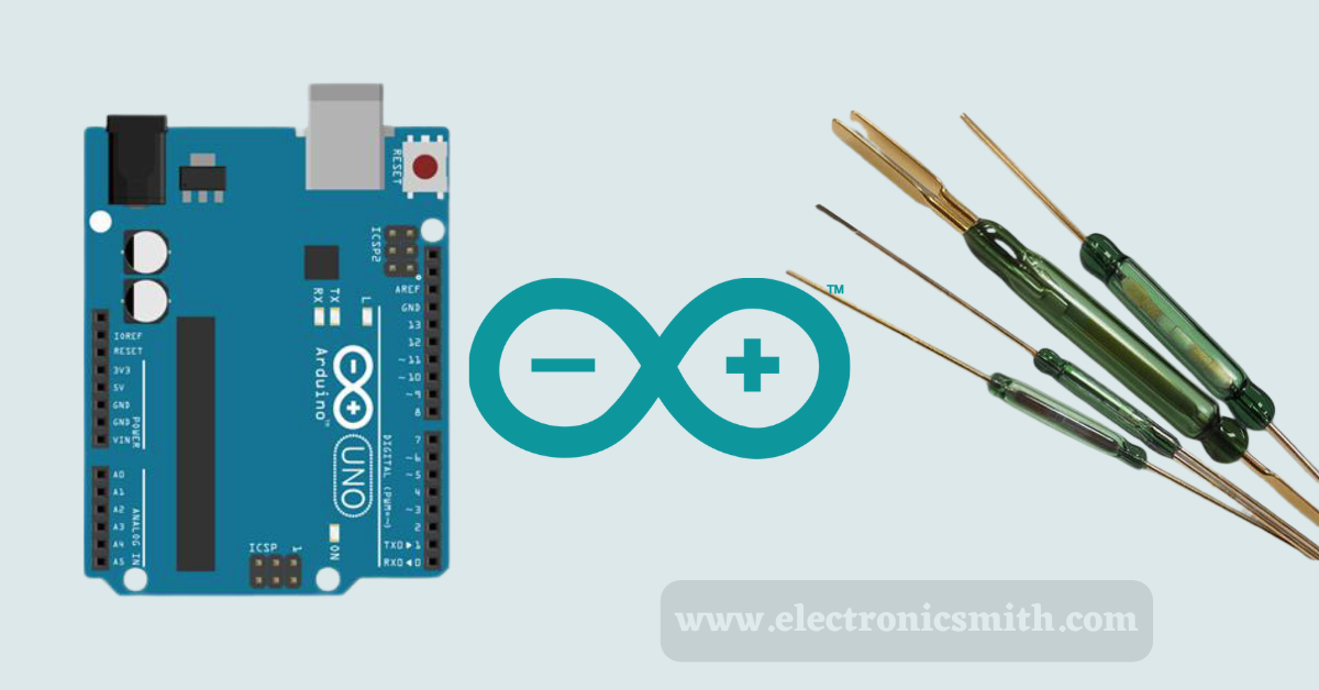
Reed switch was first discovered in 1936 by Walter B. It is an electromechanical switch-like relay operated by an applied magnetic field. Whenever you take a look at the laptop or a cellphone that flips over and opens like a clamshell, you should have noticed that when you open and close it, it goes ON or OFF accordingly. If you think there is some kind of switch connected to the hinge that finds this, yes you are right.
It is usually based on the presence or absence of a magnetic field, reed switch contacts would be either closed or open. Reed switches are almost utilized in all types of creative applications like door sensors, anemometers (detects the wind speed), etc.
Working of sensor
The most important thing to understand how reed switches function is to realize that they are a portion of a magnetic circuit and an electrical one – magnetism moves through them and electricity. As you bring a magnet near the reed switch, the whole switch becomes a part of the “magnetic circuit” involving the magnet itself.
The two contacts of a reed switch become contradictory magnetic poles, which is why they allure and snap together. It does not matter at which end of the magnet you bring near. The contacts still polarize in opposite ways and attract each other. When you take the magnet far away, the contacts segregate and return to their original position.
A reed switch like this is usually open (NO). This states that ‘normally’ when the switch is unaffected by the magnetic field, the switch is open and does not show electricity. When a magnet comes very near enough to start the switch, the contacts close, and current flows through actual reed switches that have contacts only a few microns away from each other (about ten times thinner than a human hair). So it is not possible to see the movement with our naked eyes.
Sensor’s physical appearance
- Reed Switch is normally composed of a pair of ferromagnetic (something as not difficult to magnetize as iron) flexible metal contacts, generally nickel-iron alloy (as they are not very difficult to magnetize and does not stay magnetized for very long).
- Moved apart by only a few microns, coated with a hard-wearing metal such as Rhodium or Ruthenium(Rh, Ru, Ir, or W) (to give them a longer life as they switch on and off) in a hermetically sealed (airtight) glass envelope (to keep them dust and dirt free).
Hardware Overview
The reeds are hermetically packed inside a tubular glass envelope to keep them free of dust and dirt. The hermetic board of reed switches makes them acceptable for use in explosive environments where small sparks from conventional switches would constitute a hazard. The glass tube is filled with an inert gas, usually nitrogen, or a vacuum to stop the oxidation of the contacts.
The glass tube comprises inert gas (An inert gas is a type of gas that does not undergo chemical reactions under a set of given conditions), typically Nitrogen, or in the case of very high voltage, it is just a normal vacuum. A Reed Switch has a very, very low resistance when turned off, typically as low as 50 milliohms; hence, a Reed Switch can be said to have zero power to operate it.

A metal reed is put at each end of a glass tube, and the end of the tube is warmed so that it seals around a shank portion on the reed. Green-colored Infrared-soaking glass is normally used so that an infrared heat source can concentrate the heat in the small zone of the glass tube. The glass used is of high electrical resistance and does not hold volatile components such as lead oxide and fluorides which can contaminate the contacts during the operation. The switch’s leads must be handled carefully to turn aside, breaking the glass envelope.
There are 3 types of Reed switches:
1. One Pole, one Throw, Usually Open [SPST-NO] (commonly switched off)
2. One Pole, One Throw, Normally Closed [SPST-NC] (usually switched on)
3. Single Pole, Double Throw [SPDT] (one leg is commonly closed, and one usually open can be used alternately between two circuits). Though most of the reed switches have two ferromagnetic contacts, some have only one ferromagnetic contact and one that’s non-magnetic, while some, like the original Elwood reed switch, have three. They may also be dissimilar in shapes and sizes.
Material required
| S. No. | Components used | Unit used |
| 1 | Reed switch SPST | 1 |
| 2 | Resistor 220 ohm | 1 |
| 3 | Resistor 10k ohm | 1 |
| 4 | Led (generic) | 1 |
| 5 | Multimeter | 1 |
| 6 | 9V battery (generic) | 1 |
| 7 | Breadboard generic | 1 |
| 8 | Magnet | 1 |
| 9 | Arduino nano RR3 | 1 |
Circuit connection
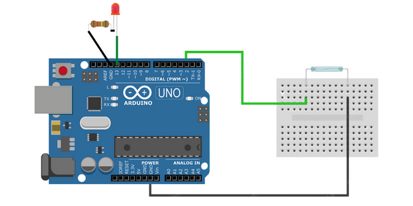
Let’s test first the Reed Switch in the absence of an Arduino. Attach a LED in series with the Reed Switch to a battery, then When a magnet is brought in proximity to the contacts, the LED lights up when the nickel-iron blades inside the switch attract each other, finishing off the circuit. And when the magnet is detached, the switch automatically returns to its open state, and the LED turns off.
After this, let us join the Reed Switch to an Arduino. Attach the LED to pin 13 of the Arduino. Then join the Reed Switch to PIN 2 and ground the other end. It also requires a 10kohm pull-up resistor joined to the same pin to allow a composed current flow to the digital input pin (Optional step). If you want, you can also utilize the internal pull-up resistor of the Arduino for this setup.
The code is very easy. Put PIN 2 as Reed_PIN and pin number 13 as LED_PIN. In the setup section, put the pin-mode of the Reed_PIN as input and LED_PIN as output. And then Finally, in the loop section, turn on the LED when the Reed_PIN goes lowest.
The same as before, when a magnet is brought in proximity to the contacts, the LED lights up, and when the magnet is detached, the switch automatically returns to an open state, and the LED turns off.

Code
const int REED_PIN = 2;	// Pin connected to reed switch
const int LED_PIN = 13;	// LED pin

void setup() {
	Serial.begin(9600);
	pinMode(REED_PIN, INPUT_PULLUP);	// Enable internal pull-up for the reed switch
	pinMode(LED_PIN, OUTPUT);
}

void loop() {
	int proximity = digitalRead(REED_PIN); // Read the state of the switch

	// If the pin reads low, the switch is closed.
	if (proximity == LOW) {
		Serial.println("Switch closed");
		digitalWrite(LED_PIN, HIGH);	// Turn the LED on
	}
	else {
		Serial.println("Switch opened");
		digitalWrite(LED_PIN, LOW);		// Turn the LED off
	}
}
Code Explanation
The code is quite self-explanatory. Initially, two constants are defined, which declare the Arduino pins to which the reed switch and built-in LED are joined.
const int REED_PIN = 2;
const int LED_PIN = 13;
In setup(), the reed switch pin is configured as an input while the LED pin is configured as an output. Also, the internal pull-up is enabled for the reed switch pin
void setup() {
	Serial.begin(9600);
	pinMode(REED_PIN, INPUT_PULLUP);
	pinMode(LED_PIN, OUTPUT);
}
In the loop(), the built-in LED is turned ON if the reed switch pin reads LOW; otherwise turned OFF.
void loop() {
	int proximity = digitalRead(REED_PIN);

	if (proximity == LOW) {
		Serial.println("Switch closed");
		digitalWrite(LED_PIN, HIGH);
	}
	else {
		Serial.println("Switch opened");
		digitalWrite(LED_PIN, LOW);
	}
}
FAQ
Who invented Reed switches?
Ans- Like great inventions, the reed switch was first born at Bell Laboratories, and discovered by Walter B. Ellwood in the mid-1930s. His obvious application for an electromagnetic switch was put in order on June 27, 1940, and was officially granted on December 2, 1941.
