
Colour sensors are widely used in the automobile, cloth, and food packaging industries. Those devices are quite complicated and expensive. So Colour sensors like TCS3200 or TCS239 are perfect modules for small projects because of their inexpensive price and simplicity. In this article, we will learn about the working and Arduino interface of these sensors.
Working of TCS3200/TCS230 Color Sensor Module
There are three primary colours RGB (Red, Green, Blue) white light consists of these three colours. We see the colours when white light falls on the object and is reflected back to a particular wavelength. We see red rose because rose absorbs all the wavelengths present in white light and only reflects red wavelength. That red wave of electromagnet spectrum falls in ower eyes and ower eyes are able to see a red rose.

TCS3200/TCS230 Have high-intensity white LEDs that projects white light on the object. The reflected light fall on the sensor, The sensor has an 8×8 array of colour sensitive filter (Bayer Filter). Each pixel is made up of 4 filters Red, Green, Blue and clear filter. Behind each pixel, there is a photodiode that senses the intensity of RGB.
you can choose types of photodiode by the following combination.
| S2 | S3 | Photodiode type |
| 0 | 0 | Red |
| 0 | 1 | Blue |
| 1 | 0 | Clear |
| 1 | 1 | Green |

An internal current-to-frequency converter converts readings from photodiodes into a square wave whose frequency is proportional to the intensity of the chosen color. The range of the typical output frequency is 2HZ~500KHZ. To scale the output frequency we have pin S0 & S1 depending on the following table.
| S0 | S1 | Output frequency scaling |
| 0 | 0 | Power down |
| 0 | 1 | 2% |
| 1 | 0 | 20% |
| 1 | 1 | 100% |
Pin Out TCS3200/TCS230
Each TCS3200/TCS230 sensor have an 8×8 array of photodiodes. 16 diodes have a red filter, 16 diodes have a blue filter, 16 diodes have a green filter and 16 diodes have clear with no filter. They all are connected parallel.

| Pin Name | Function |
| SO & S1 | frequency scaling |
| S2 & S3 | To select the color array |
| OE | Output enable |
| OUT | TTL level square wave |
| VCC | Power input (3.3v to 5v) |
| GND | Ground |
Components required
| Name | Quantity |
| Arduino | 1 |
| TCS3200/TCS230 | 1 |
| Jumper wires | As per requirement |
| RGB LED | 1 |
| LCD Display | 1 |
| Breadboard | 1 |
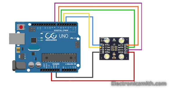
Connection
Arduino Pin no. 4 will connect with colour sensor S0. similarly, Pin no. 5 will connect to sensor S1. To select the colour array connect Arduino pin no 6 to colour sensor S2 and Arduino pin 7 to sensor pin S3.
Code to optaint row data
// Define color sensor pins
#define S0 4
#define S1 5
#define S2 6
#define S3 7
#define sensorOut 8

// Variables for Color Pulse Width Measurements
int redPW = 0;
int greenPW = 0;
int bluePW = 0;

void setup() {
	// Set S0 - S3 as outputs
	pinMode(S0, OUTPUT);
	pinMode(S1, OUTPUT);
	pinMode(S2, OUTPUT);
	pinMode(S3, OUTPUT);

	// Set Pulse Width scaling to 20%
	digitalWrite(S0,HIGH);
	digitalWrite(S1,LOW);

	// Set Sensor output as input
	pinMode(sensorOut, INPUT);

	// Setup Serial Monitor
	Serial.begin(9600);
}

void loop() {
	// Read Red Pulse Width
	redPW = getRedPW();
	// Delay to stabilize sensor
	delay(200);

	// Read Green Pulse Width
	greenPW = getGreenPW();
	// Delay to stabilize sensor
	delay(200);

	// Read Blue Pulse Width
	bluePW = getBluePW();
	// Delay to stabilize sensor
	delay(200);

	// Print output to Serial Monitor
	Serial.print("Red PW = ");
	Serial.print(redPW);
	Serial.print(" - Green PW = ");
	Serial.print(greenPW);
	Serial.print(" - Blue PW = ");
	Serial.println(bluePW);
}


// Function to read Red Pulse Widths
int getRedPW() {
	// Set sensor to read Red only
	digitalWrite(S2,LOW);
	digitalWrite(S3,LOW);
	// Define integer to represent Pulse Width
	int PW;
	// Read the output Pulse Width
	PW = pulseIn(sensorOut, LOW);
	// Return the value
	return PW;
}

// Function to read Green Pulse Widths
int getGreenPW() {
	// Set sensor to read Green only
	digitalWrite(S2,HIGH);
	digitalWrite(S3,HIGH);
	// Define integer to represent Pulse Width
	int PW;
	// Read the output Pulse Width
	PW = pulseIn(sensorOut, LOW);
	// Return the value
	return PW;
}

// Function to read Blue Pulse Widths
int getBluePW() {
	// Set sensor to read Blue only
	digitalWrite(S2,LOW);
	digitalWrite(S3,HIGH);
	// Define integer to represent Pulse Width
	int PW;
	// Read the output Pulse Width
	PW = pulseIn(sensorOut, LOW);
	// Return the value
	return PW;
}

Colour sesor connection with RGB LED

Code to change LED colour to read value
#define s0 4        //Module pins wiring
#define s1 5
#define s2 6
#define s3 7
#define out 8

#define LED_R 11   //LED pins, don't forget "pwm"
#define LED_G 10
#define LED_B 9

int Red=0, Blue=0, Green=0;

void setup()
{
   pinMode(LED_R,OUTPUT);     //pin modes
   pinMode(LED_G,OUTPUT);
   pinMode(LED_B,OUTPUT);

   pinMode(s0,OUTPUT);
   pinMode(s1,OUTPUT);
   pinMode(s2,OUTPUT);
   pinMode(s3,OUTPUT);
   pinMode(out,INPUT);

   Serial.begin(9600);   //intialize the serial monitor baud rate

   digitalWrite(s0,HIGH); //Putting S0/S1 on HIGH/HIGH levels means the output frequency scalling is at 100% (recommended)
   digitalWrite(s1,HIGH); //LOW/LOW is off HIGH/LOW is 20% and LOW/HIGH is  2%

}

void loop()
{
  GetColors();                                    //Execute the GetColors function

  analogWrite(LED_R,map(Red,15,60,255,0));      //analogWrite generates a PWM signal with 0-255 value (0 is 0V and 255 is 5V), LED_R is the pin where we are generating the signal, 15/60 are the min/max of the "Red" value, try measuring your own ones
                                               //e.g: if the "Red" value given by the sensor is 15 -> it will generate a pwm signal with 255 value on the LED_R pin same for 60->0, because the lower the value given by the sensor the higher is that color
  analogWrite(LED_G,map(Green,30,55,255,0));
  analogWrite(LED_B,map(Blue,13,45,255,0));

}

void GetColors()
{
  digitalWrite(s2, LOW);                                           //S2/S3 levels define which set of photodiodes we are using LOW/LOW is for RED LOW/HIGH is for Blue and HIGH/HIGH is for green
  digitalWrite(s3, LOW);
  Red = pulseIn(out, digitalRead(out) == HIGH ? LOW : HIGH);       //here we wait until "out" go LOW, we start measuring the duration and stops when "out" is HIGH again, if you have trouble with this expression check the bottom of the code
  delay(20);
  digitalWrite(s3, HIGH);                                         //Here we select the other color (set of photodiodes) and measure the other colors value using the same techinque
  Blue = pulseIn(out, digitalRead(out) == HIGH ? LOW : HIGH);
  delay(20);
  digitalWrite(s2, HIGH);
  Green = pulseIn(out, digitalRead(out) == HIGH ? LOW : HIGH);
  delay(20);
}
Colour Sensor Connection with LCD and display RGB value

Code
#include <Wire.h>
#include <LiquidCrystal_I2C.h>
// TCS230 or TCS3200 pins wiring to Arduino
#define S0 4
#define S1 5
#define S2 6
#define S3 7
#define sensorOut 8

// Set the LCD address to 0x27 or 0x3f for a 16 chars and 2 line display
LiquidCrystal_I2C lcd(0x27, 20, 4);

// Stores frequency read by the photodiodes
int redFrequency = 0;
int greenFrequency = 0;
int blueFrequency = 0;

void setup() {
  lcd.init();
  lcd.backlight();
  // Setting the outputs
  pinMode(S0, OUTPUT);
  pinMode(S1, OUTPUT);
  pinMode(S2, OUTPUT);
  pinMode(S3, OUTPUT);

  // Setting the sensorOut as an input
  pinMode(sensorOut, INPUT);

  // Setting frequency scaling to 20%
  digitalWrite(S0,HIGH);
  digitalWrite(S1,LOW);

   // Begins serial communication
  Serial.begin(9600);
}
void loop() {
  // Setting RED (R) filtered photodiodes to be read
  digitalWrite(S2,LOW);
  digitalWrite(S3,LOW);

  lcd.clear();
  lcd.setCursor(0,0);
  lcd.print("R      G       B");

  // Reading the output frequency
  redFrequency = pulseIn(sensorOut, LOW);

   // Printing the RED (R) value
  Serial.print("R = ");
  Serial.print(redFrequency);
  lcd.setCursor(0,1);
  lcd.print(redFrequency);
  delay(100);

  // Setting GREEN (G) filtered photodiodes to be read
  digitalWrite(S2,HIGH);
  digitalWrite(S3,HIGH);

  // Reading the output frequency
  greenFrequency = pulseIn(sensorOut, LOW);

  // Printing the GREEN (G) value
  Serial.print(" G = ");
  Serial.print(greenFrequency);
  lcd.setCursor(6,1);
  lcd.print(greenFrequency);
  delay(100);

  // Setting BLUE (B) filtered photodiodes to be read
  digitalWrite(S2,LOW);
  digitalWrite(S3,HIGH);

  // Reading the output frequency
  blueFrequency = pulseIn(sensorOut, LOW);

  // Printing the BLUE (B) value
  Serial.print(" B = ");
  Serial.println(blueFrequency);
  lcd.setCursor(13,1);
  lcd.print(blueFrequency);
  delay(100);
}