
An Accelerometer can be demonstrated as an electronic device used to measure the movement of anybody or a structure. In simple words, it measures the acceleration and vibration of anybody. It can absorb the vibrating waves released by the body and find out the point of orientation of the body. It is capable of sensing the vibrations from lowest frequency to highest frequency. It is widely used in satellites, aircraft for navigation, laptops for safety purposes, etc. In the article, we will learn about the working of the Accelerometer. After that, we also understand how to interface Accelerometer with Arduino.
How does Accelerometer work?
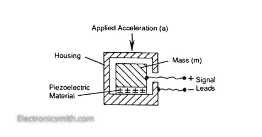
The working of the Accelerometer is based on the electromechanical sensor, which is fabricated for calculating both dynamic and static acceleration. A piezoelectric material is present in these electromechanical sensors, which experience stress due to any acceleration. When anybody or object vibrates or accelerates, this material experiences stress and moves in the direction where the effect of stress due to acceleration is high. Consequently, it starts moving or accelerating in the same phase as the vibration occurs. This acceleration results in the generation of voltage. The amount of voltage helps determine the intensity of vibration in the body. If the voltage generation is high, the object vibrates at a higher intensity and vice versa. Hence, by determining the converting the mechanical energy of the body’s vibration into the electrical energy (voltage), the Accelerometer measures any object’s movement and vibration.
Material Required
| Name | Quantity |
| ADXL335 Accelerometer | 1 |
| Arduino UNO | 1 |
| Jumper Wires | As per requirement |
Accelerometer Pinout
Before understanding the actual interface of the Accelerometer with Arduino. Let’s take a look at the pinouts of the Accelerometer:
| Pin Name | Function |
| VCC | VCC delivers power to the Accelerometer and gets connected with the 5V in Arduino. |
| X-OUT | It provides analog voltage in the form of output, and this voltage will remain proportional to the acceleration on X-axis. |
| Y-OUT | It provides analog voltage in the form of output, and this voltage will remain proportional to the acceleration on Y-axis. |
| Z-OUT | It provides analog voltage in the form of output, and this voltage will remain proportional to the acceleration on the Z-axis. |
| GND | This pin gets connected with the GND in the Arduino. |
Connection with Arduino
Now, let’s understand the wiring of the Accelerometer with the Arduino for understanding its interface.

| Accelerometer | Arduino |
| VCC | 5v |
| GND | GND |
| X-OUT | A0 |
| y-OUT | A1 |
| z-OUT | A2 |
Code
const int xInput = A0;
const int yInput = A1;
const int zInput = A2;

// initialize minimum and maximum Raw Ranges for each axis
int RawMin = 0;
int RawMax = 1023;

// Take multiple samples to reduce noise
const int sampleSize = 10;

void setup()
{
	analogReference(EXTERNAL);
	Serial.begin(9600);
}

void loop()
{
	//Read raw values
	int xRaw = ReadAxis(xInput);
	int yRaw = ReadAxis(yInput);
	int zRaw = ReadAxis(zInput);

	// Convert raw values to 'milli-Gs"
	long xScaled = map(xRaw, RawMin, RawMax, -3000, 3000);
	long yScaled = map(yRaw, RawMin, RawMax, -3000, 3000);
	long zScaled = map(zRaw, RawMin, RawMax, -3000, 3000);

	// re-scale to fractional Gs
	float xAccel = xScaled / 1000.0;
	float yAccel = yScaled / 1000.0;
	float zAccel = zScaled / 1000.0;

	Serial.print("X, Y, Z  :: ");
           Serial.print(xRaw);
	Serial.print(", ");
	Serial.print(yRaw);
	Serial.print(", ");
	Serial.print(zRaw);
	Serial.print(" :: ");
	Serial.print(xAccel,0);
	Serial.print("G, ");
	Serial.print(yAccel,0);
	Serial.print("G, ");
	Serial.print(zAccel,0);
	Serial.println("G");

	delay(200);
}

// Take samples and return the average
int ReadAxis(int axisPin)
{
	long reading = 0;
	analogRead(axisPin);
	delay(1);
	for (int i = 0; i < sampleSize; i++)
	{
	reading += analogRead(axisPin);
	}
	return reading/sampleSize;
}