Setup and Loop are the two main pre-define functions of Arduino but they occupy a lot of memory. A simple blink code occupies 925 bytes of memory. The question is how to code Arduino without these functions and save memory. Also, is it possible to do so?
Coding Arduino without void setup() & void loop() is possible. In this article, we are going to modify the blink example code without void loop() and void setup() function. Also, optimize the code and reduce the space of the Arduino blink sketch.
Material Required
Hardware
| Part Name | Quantity |
| Arduino UNO | 1 |
| LED | 1 |
| 220 OHM Resistor | 1 |
| Jumper Wires | APR |
| Breadboard | 1 |
Software
| Arduino IDE | Link |
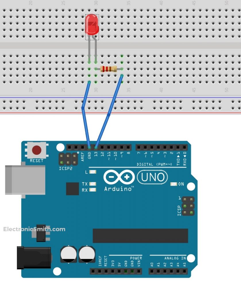
Connection
This is a part of the Arduino code basics. The connection is very easy for Arduino blink, connect everything as shown in the diagram below.
Arduino Blink Tutorial Old Code
This is the Arduino blink program which toggles a led between HIGH and LOW with a delay of 1 second. Arduino code language is C++ and there are predefined functions to make it easier for coding.
void setup()
{
pinMode(LED_BUILTIN, OUTPUT);
}

void loop()
{
digitalWrite(LED_BUILTIN, HIGH);
delay(1000);
digitalWrite(LED_BUILTIN, LOW);
delay(1000);
}
How to Write Arduino Code Without Setup and Loop Explanation
- Instead of using the pin mode, we can directly assign resistor DDRB and the hexadecimal value. As I did in this step.
void setup()
{
DDRB = 0xff;
}
- Similarly, remove digital and write with PORTB and assign it hexadecimal high and low.
void loop()
{
PORTB = 0xff;
delay(1000);
PORTB = 0x0;
delay(1000);
}
- Arduino has its main function that calls the loop, setup, and other functions. So here, we’ll write the main functions and try to toggle between high and low. Also, we put this to infinite while on loop.
int main()
{
  DDRB = 0xff;
  while (true)
      {
       PORTB = 0xff;
       delay(1000);
       PORTB = 0x0;
        delay(1000);
       }
}
- Delay is also a predefined function. We are not using any libraries so we can’t use delay directly. Here, we try to make our own delay. For that I make a loop to simulate the delay. During the testing, I observe that only one loop executes and stops because the loop returns with nothing. So, I solved this problem by passing an empty string.
This Arduino code works fine as it successfully toggles the pin between high and low.
int main()
{
DDRB = 0xff;
while (true)
{
PORTB = 0xff;
for (long i = 0; i<1000000; i++)
{
  asn("");
}
PORTB = 0x0;
for (long i = 0; i<1000000; i++)
{
asn("");
}
}
}
Final Code
There is a PIN method that allows toggling the pin state depending on the preview state. So, I use the method which makes my code shorter and less in size.
int main()
{
  DDRB = 0xff;
  while (true)
{
    PINB = 0xff;
    for (long i = 0; i < 500000; i++)
{
      asm("");
    }
  }
}
Everything About Ports
PORTD maps to Arduino Digital pins 0 to 7
- DDRD- The Port D Data Direction Register – read/write
- PORTD- The Port D Data Register – read/write
- PIND- The Port D Input Pins Register – read-only
PORTB maps to Arduino digital pins 8 to 13. The two high bits (6 & 7) map to the crystal pins and are not usable.
- DDRB- The Port B Data Direction Register – read/write
- PORTB- The Port B Data Register – read/write
- PINB- The Port B Input Pins Register – read-only
PORTC maps to Arduino analog pins 0 to 5. Pins 6 & 7 are only accessible on the Arduino Mini.
- DDRC- The Port C Data Direction Register – read/write
- PORTC- The Port C Data Register – read/write
- PINC- The Port C Input Pins Register – read-only
Each bit in these register corresponds to a single pin. Such as DDRB, PORTB, and PINB refers to the low bit pin PB0 (digital pin 8). For a complete mapping of the Arduino pin number to ports and bits, see the diagram for your chip i.e. ATmega8, ATmega168. (Note that some bits of a port can be used for things other than I/O, be careful and do not change the values of register bits corresponding to them.)