The Arduino Micro is a smaller version of the Arduino Leonardo board. Like Arduino Leonardo, it also has an ATmega32U4 microcontroller And consists of digital input/output pins, a micro-USB port, a crystal oscillator, an ICSP header pin, a RESET button, etc.
It contains everything needed to support the microcontroller, we just only need to connect it to a pc through a USB cable and we are ready to go.
Arduino Micro Board Layout
ATmega32U4
The ATmega32U4 is a microcontroller chip developed by “Atmel”. It is a low-power 8-bit AVR RISC-based microchip that contains a 32-kilobyte self-programming flash program memory, 2.5 kilobyte SRAM, 1 kilobyte EEPROM, USB 2.0 full-speed/low-speed device, and a 12-channel 10-bit A/D-converter.
Crystal Oscillator
The Arduino Micro contains a Crystal oscillator having a frequency of 16MHz. It generates the clock signal in the microcontroller.
The Crystal oscillator is used to provide the basic timing and control to the board.
Micro USB Port
The Arduino Micro comes with a Micro USB 2.0 port which allows us to establish the connection between the board and the computer. It is very important in programming the Arduino Micro board.
In-Build LED 13
In Arduino Micro, a built-in LED which is green in color is connected to the digital pin 13. This LED can be controlled by switching the pin to High and Low.
Serial communication LEDs
RX LED
In the Arduino Micro board, there is an RX LED connected to digital pin 17 which shows the receiving of data. This LED can be controlled by switching the pin to high or Low.
TX LED
In the board, there is a TX LED which is connected to the digital pin 30 which represents the transmission of data. This LED can also be controlled by switching the pin to high or low.
Specifications of Arduino Micro
The Specifications of Arduino Micro are listed below

| Microcontroller | ATmega32U4 |
| Operating Voltage | 5V |
| Input Voltage (recommended) | 7-12V |
| Digital I/O Pins | 20 |
| PWM Channels | 7 |
| Analog Input Channels | 12 |
| DC Current per I/O Pin | 20 mA |
| DC Current for 3.3V Pin | 50 mA |
| Flash Memory | 32 KB (ATmega32U4) of which 4 KB is used by the bootloader |
| SRAM | 2.5 KB (ATmega32U4) |
| EEPROM | 1 KB (ATmega32U4) |
| Clock Speed | 16 MHz |
| LED_BUILTIN | 13 |
| Length | 48 mm |
| Width | 18 mm |
| Weight | 13 g |
Arduino Micro Pinout Description
The Arduino micro has 20 digital Input/Output pins. From these 20 Digital Input/Output pins 7 pins are Pulse Width Modulation(PMW) pins and 12 pins are Analog Input pins. All pins are elaborated in the following table.
| Arduino Nano Pin | Pin Name | Type | Function |
| 1 | D1/TX | I/O | Digital I/O PinSerial TX Pin |
| 2 | D0/RX | I/O | Digital I/O PinSerial RX Pin |
| 3 | RESET | Input | Reset ( Active Low) |
| 4 | GND | Power | Supply Ground |
| 5 | D2/SDA | I/O | Digital I/O Pin |
| 6 | D3/SCL | I/O | Digital I/O Pin |
| 7 | D4 | I/O | Digital I/O Pin |
| 8 | D5 | I/O | Digital I/O Pin |
| 9 | D6 | I/O | Digital I/O Pin |
| 10 | D7 | I/O | Digital I/O Pin |
| 11 | D8 | I/O | Digital I/O Pin |
| 12 | D9 | I/O | Digital I/O Pin |
| 13 | D10 | I/O | Digital I/O Pin |
| 14 | D11 | I/O | Digital I/O Pin |
| 15 | D12 | I/O | Digital I/O Pin |
| 16 | AREF | Input | ADC reference |
| 17 | A0 | Input | Analog Input Channel 0 |
| 18 | A1 | Input | Analog Input Channel 1 |
| 19 | A2 | Input | Analog Input Channel 2 |
| 20 | A3 | Input | Analog Input Channel 3 |
| 21 | A4 | Input | Analog Input Channel 4 |
| 22 | A5 | Input | Analog Input Channel 5 |
| 23 | +5V | Output or Input | +5V Output (From On-board Regulator) or+5V (Input from External Power Supply |
| 24 | RESET | Input | Reset ( Active Low) |
| 25 | GND | Power | Supply Ground |
| 26 | VIN | Power | Supply voltage |
Power Pins of Arduino Micro
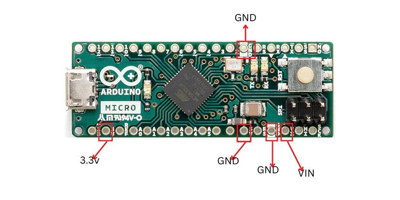
Vin
It is the input voltage pin of Arduino Micro. A Vin pin can be used to power up the Arduino Micro board.
When a certain voltage(5 volts) is given via the power jack to power the board, this voltage shows up at the Vin pin. The Vin pin and Power jack terminal are connected to each other internally.
5V out Pin
The 5V pin of Arduino Micro is used to generate a regulated output of 5v for the externally connected components. The power source of the 5V pin of the Arduino Micro board is a USB connector and the Vin pin.
A 5-volt voltage regulator is used to step down the input voltage coming from the Vin pin or power jack to a steady 5V. This 5V output from the voltage regulator is then connected to the 5V pin of the Arduino Micro board.
3.3v out Pin
The 3.3v Pin of the Arduino Micro board is used to generate an output voltage of 3.3v.
GND Pins
There are 2 ground pins available in the Arduino Micro board. The ground pins are used to ground a circuit.
Digital I/O (Input output pins )
Digital Pins
The Arduino Micro board contains 20 digital input/Output pins which are used as an Input or Output. The Digital I/O pins operate at 5 volts of voltage. The digital pins of Arduino Micro are able to read one of the two states which are ”High” when the electric signal is present and ”Low” when the electric signal is absent. This kind of input is usually known as digital or binary and these states are referred to as HIGH or 1 and LOW or 0.

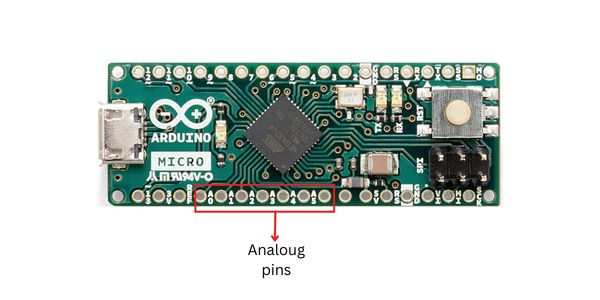
Analog Pins
The Arduino Micro board consists of 12 analog input Pins, which are labeled as ADCX where X represents the Pin number.
Every pin of the Arduino Micro board is connected to an inbuilt ADC of 210 bit(210 bit = 1024 different values) resolution.
Pulse Width Modulations(PMW) Pins of Arduino Micro
The Pulse width Modulation(PMW) Pins are used to convert the digital signals into analog signals.
7 Pins from the digital pins are PWM Pins, they are numbered as:-
3, 5, 6, 9, 10, 11, 13.
Each PWM Pin provides 8-bit output. In order to generate the PWM output we have to use a syntax “analogwrite(PWM Pin, PWM value)”. PWM values vary between 0 volts to 255 volts.

Communication Pins of Arduino Micro
SPI Pins of Arduino Micro Board
SPI stands for “Serial Peripheral interface”. These pins are used by the microcontroller to communicate with other peripheral devices. The communications are supported by the SPI pins which are present on the ICSP header using the SPI library.
Two Wire Interface(TWI)/I2C Pins of Arduino Micro:-
The I2C stands for “Inter-Integrated Circuit”. I2C is a two-wire serial communication protocol. It uses two pins for sending and receiving the data, a serial clock(SCA) pin and a serial data (SDA) pin.

SCA
It stands for Serial Clock. It is defined as the pin that transmits the clock data between the devices. It is used for synchronization purposes. The Serial Clock is provided by the master device.
SDA
It stands for Serial Data. This pin is used by both the slave and master device to send and receive the data in between. This is the reason why it is also called a data line, while SCL can be called a clock line.
ICSP Pins of Arduino Micro Board
ICSP stands for “In-Circuit Serial Programming”. The header pins of ICSP are used to program the firmware of the Arduino Micro Board. The important firmware updates with new capabilities are sent in through the microcontroller with the help of the ICSP header. The ICSP header consists of 6 pins.
UART Pins
In the Arduino Micro board, UART Pins are used to transmit and receiving data. 0 (RX) is used to receive the data while 1 (TX) is used to transmit (TX) TTL serial data using the ATmega32U4 hardware serial capability.
External Interrupts of Arduino Micro
Arduino micro consists of 4 external interrupts
3 (INT 0)
2 (INT 2)
0 (INT 3)
1 (INT 4).
The interrupt pins can be configured to trigger the interrupt if any of the following changes occur:
- a low value
- a rising edge
- falling edge
- a change in value.
AREF Pin
This pin is used for the reference voltage for the analog inputs. AREF pin is used with the function analogReference().
RESET Pin
For Resetting the board a low or 0 is given to this pin.
1 thought on “Arduino Micro pinout and their function”