I made a Digital Clock using RTC DS1302, Arduino, and Dot Matrix and when I posted about it on Instagram, my inbox was flooded with great responses, asking me for its tutorial. So, I am publishing this article. This will surely be helpful for you to make your own desk clock.
Material Required
- Arduino Nano
- Max7219 dot matrix module
- RTC DS3231
- Buck Pin
- Soldering iron
- Soldering wire
- Universal PCB
- Wires
Configure RTC DS3231
RTC (Real-Time Clock) DS3231 is an I2C (Inter-Integrated Circuit) protocol based clock. It has an integrated temperature-compensated crystal oscillator and a crystal that makes is extremely accurate.
To work with this module you require an RTClib library. Download it and add it to the Arduino IDE. For adding it, first open your Arduino IDE, then go to Sketch> Include Library>Add .zip library. Now, navigate to your downloaded location and click on Open. After doing this, restart the Arduino IDE software.
Connect the module with your Arduino as shown in schematics. The connection is the same for Arduino nano and UNO. I2C pins are also the same on both boards. In case, you have any other board follow the table below for connecting it.
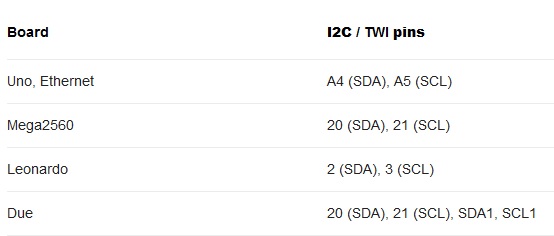
Connect the Arduino 5v to RTC DS3231, GND to GND, A4 to SDA , and A5 to SCL.

Let’s upload an example code that will give you a date and time on the serial monitor. Go to File>Example>RTClib>Timestamp.

Now, open the serial monitor by clicking on the top-right magnifying lens icon or Ctrl+Shift+M or either go to Tools>Serial Monitor. Make sure that the Arduino is connected and baud rate is 57600.
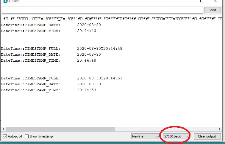
The output is the current date and time. The time is in 24 hours clock format. You can convert it into 12 hrs clock by simply subtracting 12 only when the actual time is greater then 12.
MAX7219 Dot Matrix Module
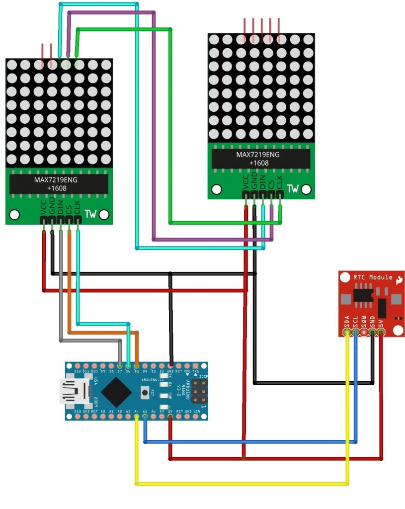
We are using an 8*8 matrix for the digital time clock. This module has a set of 64 LEDs arranged in the 8*8 matrix. I am using the max7219 dot matrix module. The connection with this module and Arduino is very simple, so I’m using this module.

You will require MaxMatrix library, so download and install it in your Arduino IDE software. We are using 2 matrix modules, one is for hours and the other is for minutes.
| Arduino | Matrix1 in | Matrix1 out | Matrix2 In |
| D7 | DIN | Dout | Din |
| D6 | CLK | CLK | CLK |
| D5 | CS | CS | CS |
Download this code and upload it to your Arduino. A few digital clock font will appear on your matrix screen.
Assembly on the Breadboard
I prefer to verify the circuit initially on the breadboard. Then, Mount every component on the breadboard, and connect them all according to the schematics.
To download main code, Click Here…
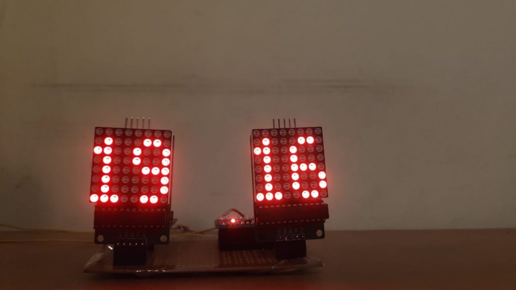
If everything is correct, then the final output will look like this.

Assembly on PCB
Now, its time to make the same connection on PCB.

Then, switch on the power of the circuit and the current time will be displayed this way.